Reading Between the Lines: The Language of Structural Engineers
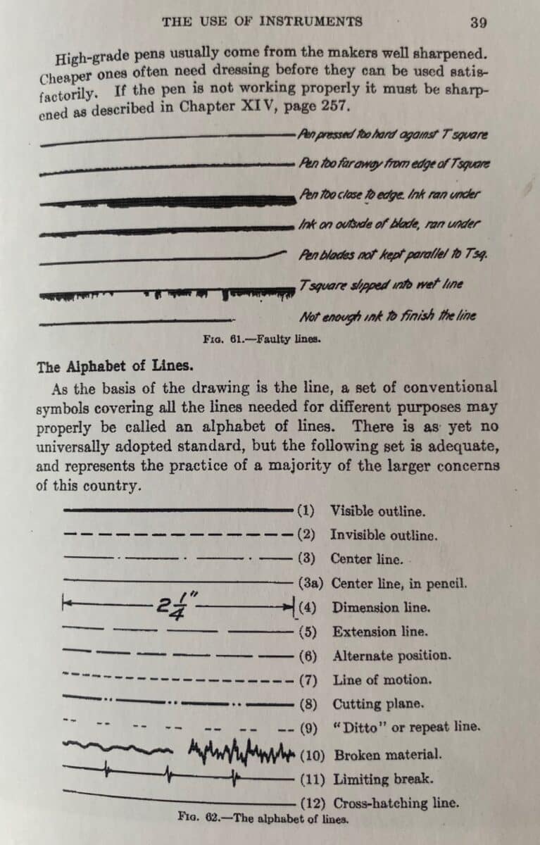
A version of the phrase ‘engineering drawing is a universal language of signs and symbols’ appears in countless engineering drawing textbooks starting in the early twentieth century and continues today. A particularly evocative iteration published in the 1960s states: ‘[Engineering drawing] is a universal language; for the reader may be an American and the draftsman French, but the Frenchman can make the drawing so that the American can read it.’[1] Not only is this visual language universal, the textbook suggests, but its standardisation also transcends cultural differences. The notion that drawing is a form of language is hardly new territory for discussion, but the distinct way in which engineering representation is often mythologised as being rational, highly codified and culturally agnostic is a flawed premise.[2]
On the contrary, engineering representation is often loosely defined, and has come to be shaped by a variety of technological, economic, environmental, and cultural forces. These influences are often embedded and legible in the drawings themselves, and make evident the importance of drawing as both a reflection and agent of engineering thinking and design. This essay explores some of these influential forces at a general level and examines the way they play out in drawings by three of the engineers featured in the exhibition: Mamoru Kawaguchi, August Komendant, and Mahendra Raj.
Structural drawings describe the primary supporting elements of a building and how they are designed to resist gravity and lateral loads through their connections and assemblies. While architectural drawings use poche and section to define the mass and the interrelationship of parts that allow for the movement of people through a space, structural drawings divide buildings into points, lines, and planes to describe the flow of forces from the roof to the ground in a way that can be rationalised geometrically and mathematically. Concrete, steel, and timber have distinct drawing conventions that reflect their load path mechanics and the way they are put together in the field or the shop. These conventions, however, can vary widely between structural engineers, both domestically and abroad.
As far as languages go, engineering drawing is young. Historians Ken Baynes and Francis Pugh suggest that the birth of engineering drawing was the Industrial Revolution. They note, ‘Although it is possible to trace roots back to naval architectural draftsmanship and scientific and technical illustration at the time of the Renaissance, it was a distinctive form of production—the division of labour—that made engineering drawing essential.’[3] While Baynes and Pugh write primarily about mechanical engineering (machines, locomotives, etc), structural engineering followed a similar trajectory.
New technologies and manufacturing techniques necessitated advanced drawing methods for specifying rolled steel sections, standardised wood connection hardware, and steel reinforcing in concrete structures. Each material comes with specific labour and fabrication requirements, as well as analytical challenges. Differences in local fabrication practice as well as material availability caused technical drawing standards to diverge both domestically and internationally, and sometimes these differences could produce miscommunication between engineers, even those with a shared spoken language.[4] Within the United States alone, technical drawing practice differs according to factors like local environmental conditions (earthquakes, wind, flooding etc) and legal jurisdictions.[5] Even as drawing practice fluctuated, literacy in this developing graphic language was essential. Technical drawing became a key subject in every aspiring engineer’s education, and was the bedrock of an emerging professional class in the late nineteenth and early twentieth centuries.[6]
Yoyogi National Gymnasium, Mamoru Kawaguchi
Mamoru Kawaguchi (1932–2019) designed the structure for the 1964 Olympic Yoyogi National Gymnasium while working in the office of the prominent engineer Yoshikatsu Tsuboi. Kawaguchi has since been widely recognised for his innovative approach to construction sequencing and his development of hybrid structural systems, including unconventional uses of structural materials like pre-stressed stone, folded spatial structures, and mesh-reinforced air structures. The Yoyogi stadium is no exception; the structure is a distinct manifestation of Kawaguchi’s interests and expertise.
Kawaguchi once wrote, ‘Some designers are enamoured of the behaviour of a structure only after it is completed, but I think the way in which a structure is constructed is very important as well in terms of rationality and economy.’[7] Starting in the 1980s, he developed a series of mechanical structures he coined pantadomes. The pantadomes are folded into unique geometries so they can be lifted in place with a crane or hydraulic jacks. He called them pantadomes because their hinge mechanism is similar to that of the now obsolete drawing instrument, the pantograph—an early copying device used to duplicate the motion of a drawing utensil.[8] It’s interesting to think about Kawaguchi’s exposure to these instruments, which were long outdated by the time he designed the pantandomes, but might have been circulating during his studies at the University of Tokyo. Others have written about the unique pedagogy in Japan, where engineers and architects are educated together, and one could imagine that this shared experience with the tools and craft of drawing could have influenced Kawaguchi’s approach to structural design and representation.[9]
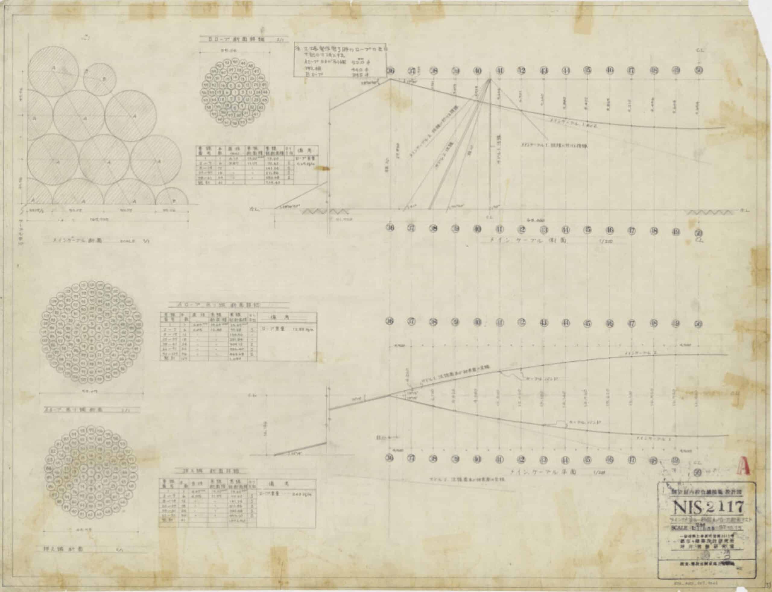
The drawing set for the Yoyogi stadiums is immaculately detailed. It toggles impressively between scales and material, ranging from line diagrams of steel cable geometry to colour-coded concrete framing plans and intricate mechanical drawings of the cast steel joints. Many of the drawings are organised by a single component or a building zone cut in several directions: the skylight, the cable bundle, the auditorium stands, the cast connections, and so on. Unlike a ‘piece’ drawing in the American sense, where a single element is drawn in isolation, the drawings for Yoyogi often combine and group structural systems on a page.[10]
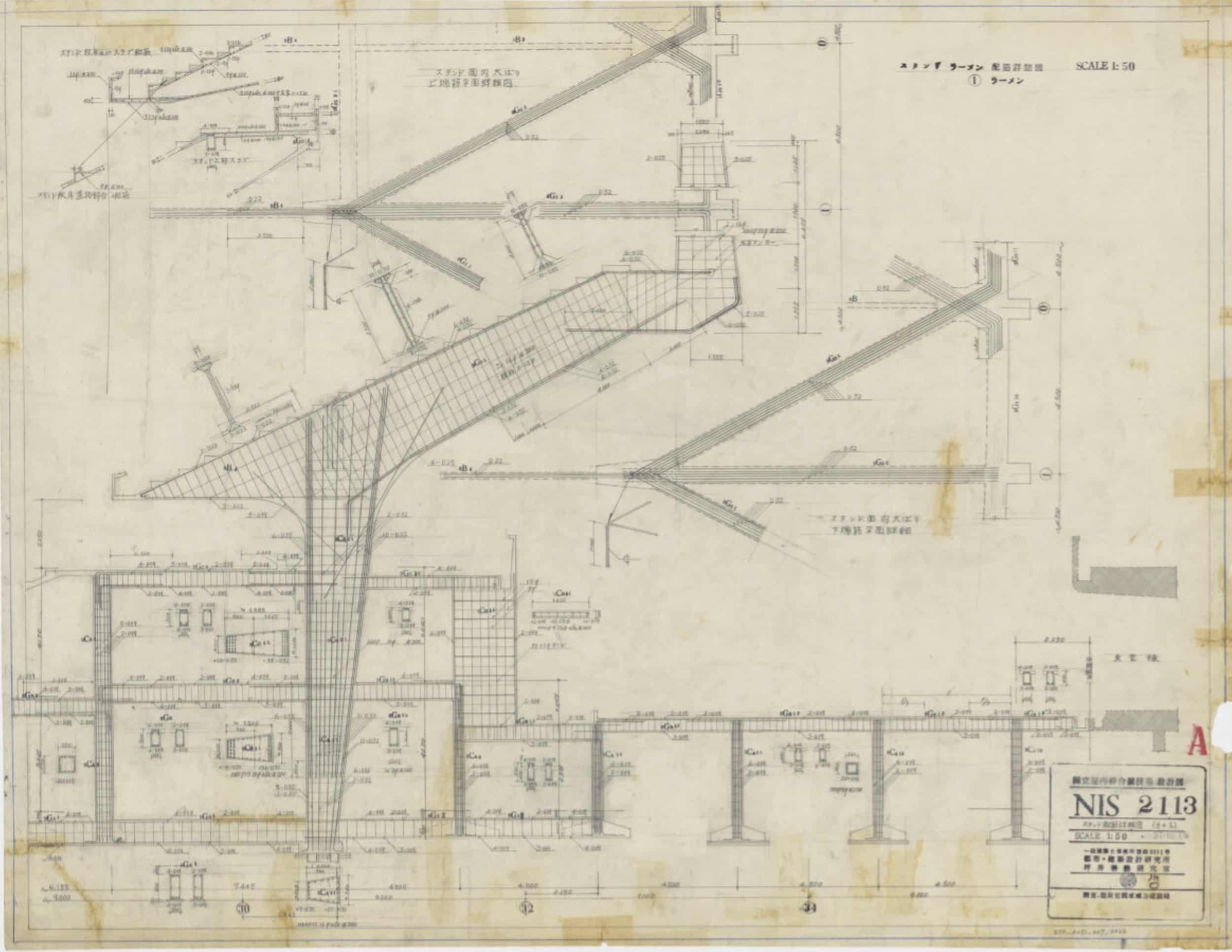
While the roof usually gets all the attention, the reinforced concrete stadium structure is also noteworthy. Rather than schedule the reinforcement numerically in a table, it’s almost all graphically represented. The building is full of unique geometry that requires sharp bends and hooks, and by drawing each configuration, there is less room for misinterpretation. A sheet like NS2113 is particularly striking in the way plans and sections are distributed across the page to tell a story about the reinforcing system for the stadium. A representative section showing the vertical gravity system is indicated at the left of the page, with two partial framing plans above and to the right indicating the horizontal system. Beam sections are pulled off the primary drawing at a diagonal, parallel to their span direction, so that their reinforcement can be read distinctly from the overall section. Rather than spread the details across the set as one might expect, they are clustered on the same sheet, providing a concise indication of how the stadium is supported vertically and spans in and out of the page.
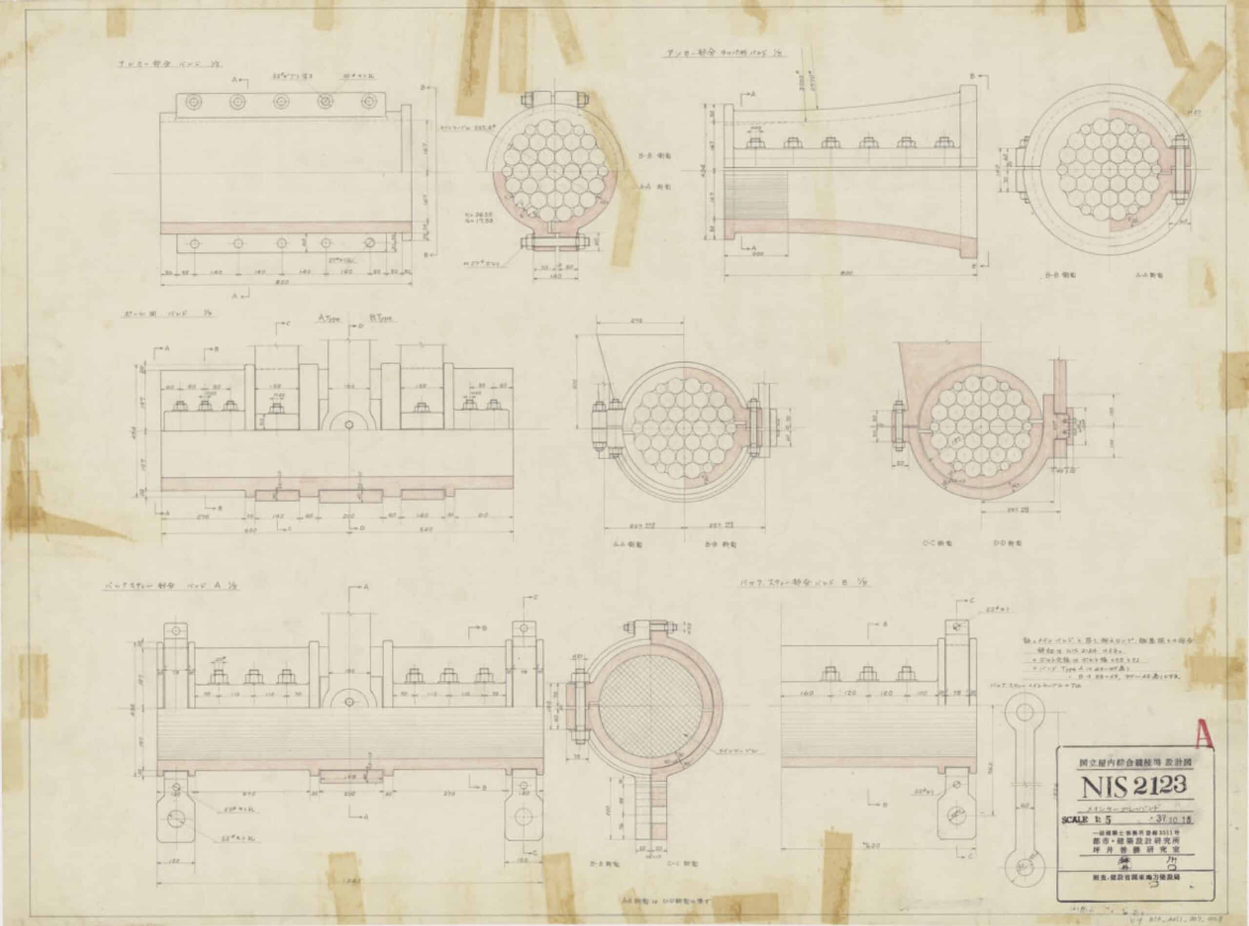
Kawaguchi designed steel castings to control the movement of the roof cables around the skylight, which were expected to experience large deflections during the construction. The castings were critical to the success of the project, and Kawaguchi developed physical models to test their rotation.[11] These connections are represented at a large scale and detailed like elaborate machine drawings. Lines of symmetry are drawn to represent the castings in section and elevation simultaneously, and this ‘halving’ operation seems to reference the symmetry of the casting mould itself. The precise geometry and curvature of these components are so important to their operability that small geometry diagrams showing their underlying radii and curvature are also indicated on the sheet. The castings represent a significant engineering contribution in their tectonics and mechanical innovation, and their representation reveals their operability in a way that’s difficult to comprehend in the completed building.
Kimbell Art Museum, August Kommendant
The drawings for the Kimbell Art Museum were produced in two parts by two engineers: Preston M. Geren (1891–1969) and August Komendant (1906–1992). Preston M. Geren & Associates was the architect and engineering firm selected by the client to be Louis Kahn’s local partner. Komendant had worked with Kahn on the Richards Medical Research Laboratories and the Salk Institute for Biological Studies, and Kahn asked him to do some early consulting on the Kimbell. Geren was the professional contractually obligated to do the engineering, however, so Komendant eventually stepped aside. As the design work proceeded, Geren and Kahn’s relationship became strained over numerous project delays, cost overruns, and the complexity of the design, all of which threatened the successful completion of the project. At a critical juncture toward the end of the design phase, Komendant was asked to engineer the upper level and roof structure in order to proceed with a structural system that better aligned with Kahn’s architectural intent.[12]
Part of the magic of the Kimbell is that the structure is not what it seems. The famous cycloid shells that make up the roof look like a system of arches, but actually they behave somewhere between a beam and an arch, spanning along the length of the structure as well as the traverse direction.[13] The beams that carry the mechanical ducts at the base of the cycloids appear to support the shells, but in reality, the shells carry the beams, and the beams just stiffen the cycloids.[14] There are also a number of deep ‘wall beams’ which look like walls but in fact span longitudinally between columns. Regarding the wall beams, Komendant explains proudly that he eliminated a number of the columns and walls supporting the upper floor level because they were not structurally necessary. He says simply of this decision: ‘The 104-foot long heavy walls could be designed as post-tensioned beams.’[15] And so they were.
While there is clear pleasure in these games of structural performance, Komendant also values the legibility of the system. In his writings he qualifies the Kimbell in terms of its ‘honesty,’ moralising the expression of the load path.[16] Important clues are distributed throughout the museum to convey the mechanisms of the structure. For instance, the arches at the end of the cycloid shells (which do behave as arches) are accentuated by the ‘lunette’ window reveal between the arch and end walls, so that it’s evident the wall is not contributing to the arch action. There is another glass separation between the top of the ‘wall beams’ and the bottom of the cycloid, lest anyone get confused and think the shell is supported by the longitudinal beams, which in turn are masquerading as walls.
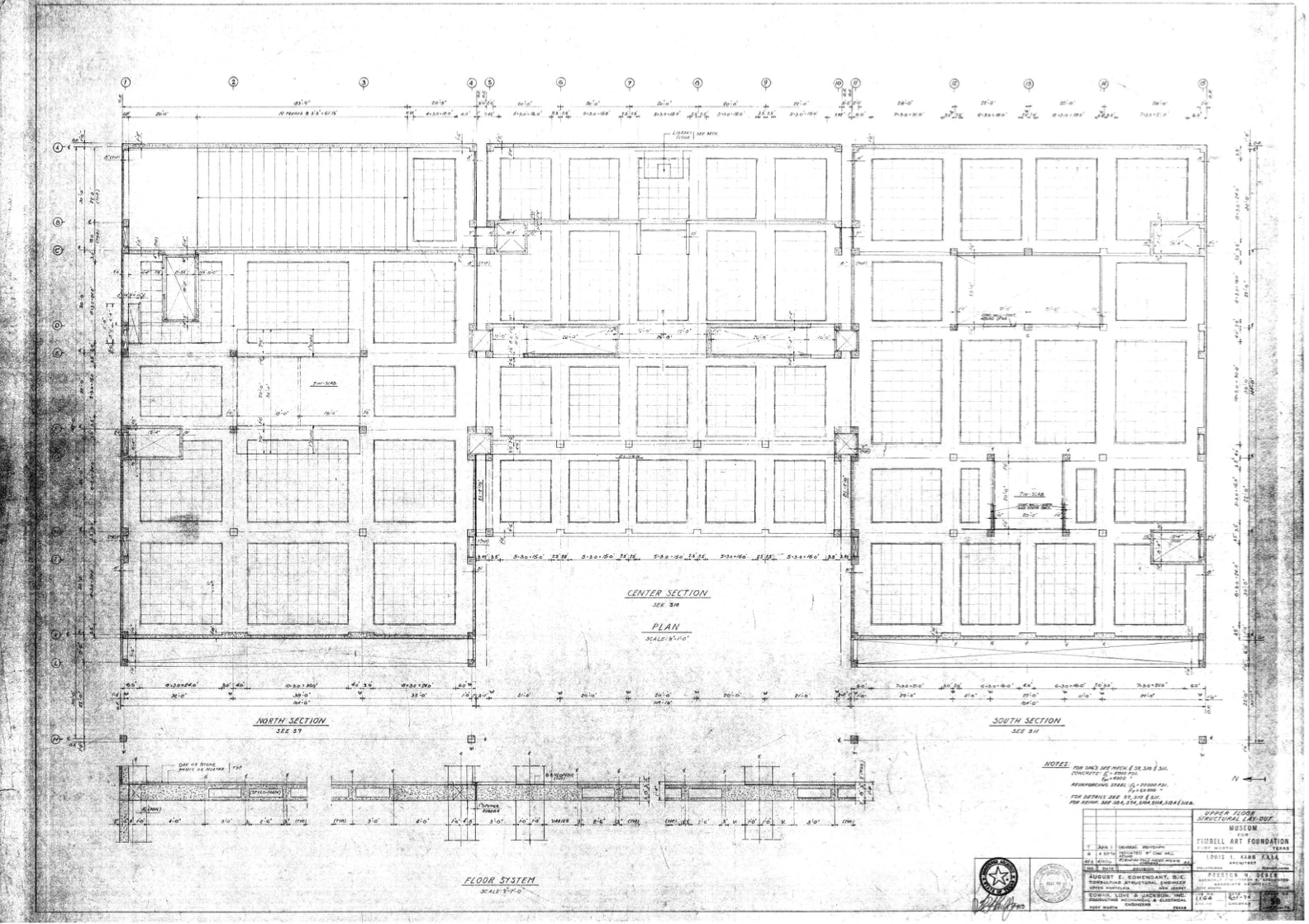
The drawings toy with this same dichotomy between structural clarity and ambiguity on a number of levels. For one, there is a striking difference between Komendant’s and Geren’s approach to graphic notation. Geren’s drawings are full of notes, dimension strings, column numbers, and beam labels. The first few pages of the set describing the foundation and lower level (all within Geren’s scope of work) are dense with information. Komendant entirely disregards the column numbering and dimensions put in place by Geren and establishes a numbered and lettered grid over the top of Geren’s lower-level columns. Compared with Geren’s 5 sheets for the foundation and lower level, Komendant has 20 drawings in total, 11 for the upper level and 9 for the roof. Komendant’s framing plans have hardly any notes, and instead, he establishes the overall structural system and geometry in a series of framing plans. Subsequent drawings focus on the structure in partial plans (North, Centre, South) and sections to describe the concrete reinforcing in each direction. While Geren’s drawings describe everything in a few compact pages, Komendant’s set reproduces the same framing plan over and over, cutting serial sections at different levels and orientations. The set gives the impression of a building being worked through and tested in the drawing itself.
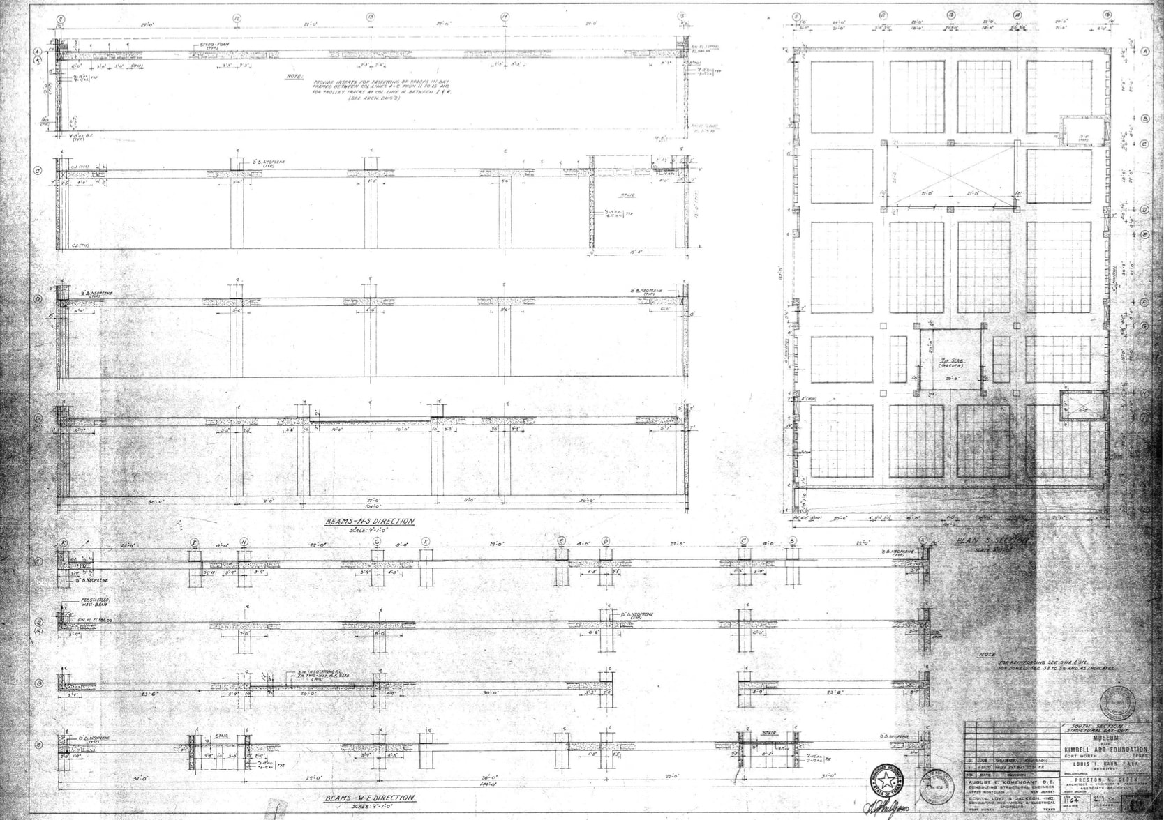
Given the complex geometry of the post-tensioning strands in the wall beams and cycloids, most of these drawings are strictly necessary; however, it also seems Komendant utilises the successive sections to articulate the load path of the whole building. By sequentially cutting through the cycloid shells with a dark pencil hatch, he has ample opportunity to demonstrate their dramatic spanning and support conditions, which might not otherwise be legible. Sheet S15 is an example where many of the structural sleights of hand are examined on a single sheet. The drawing shows the condition of the end arches and the gap where they meet a wall, the gap at the wall beams, the thinness of the cycloid shells, a movement joint and the double-skin floor.
Unlike Kawaguchi, however, Komendant resists representing the structure in small segments. The set rarely focuses on a single piece of the structure but rather uses sequence and section to explain which elements support each other and which elements span.
Hall of Nations, Halls of Industries, Mahendra Raj
Mahendra Raj (1924) began his career as a civil engineer in India, and was thrown headfirst into structural engineering when he was assigned to work on the Chandigarh High Court and Secretariat, designed by Le Corbusier. Around 1960 he started his own practice, and has since become known for his vast archive of unique and innovative structural designs, often in reinforced concrete, making effective and intelligent use of the material and methods of construction.[17]
The Hall of Nations and associated exhibition halls in New Delhi were commissioned to commemorate the 25th anniversary of India’s independence from British colonial rule. A series of cast-in-place concrete space frames, the buildings represent the first such material adaptation of a space frame structure. Cast-in-place concrete, which can be imprecise and difficult to form in situ, was a daring choice for this project. Raj studied alternatives like steel, precast concrete, and combinations thereof, but because of the scarcity of available materials and specialised labour, cast-in-place concrete was the only viable choice to maintain the cost and schedule. Within these constraints, Raj developed an effective way to design not only the structure, but also the construction sequencing. Raj had to analyse the structure several times over and under many loading conditions to account for the different ways it could behave during the course of construction.[18]
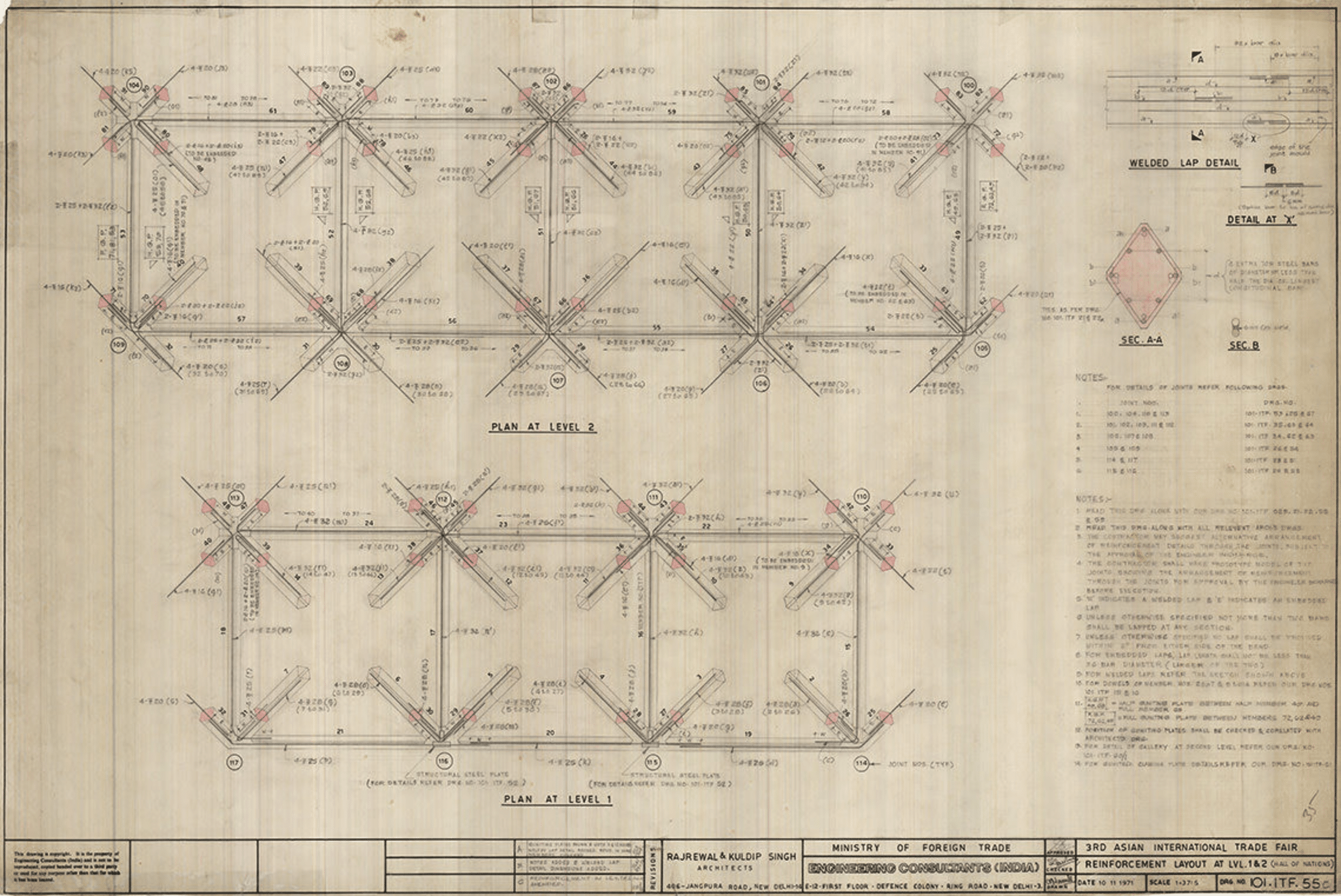
The drawings reflect the effort and planning that went into realising a project with such an unorthodox material strategy. The drawings are not only rigorous and systematic, but also make elegant use of the page, taking advantage of symmetries in the structure to demonstrate the economy of the building form. The set includes a single drawing that names every straight member and every joint, setting out the geometry of the entire Hall of Nations with one overall plan and 9 partial plans along its lines of symmetry. The sheet includes a faint sketch of the basic pyramid that governs the form of the entire structural and architectural system—a subliminal message that this massive structure can be broken into something comprehensible. The patterning and nomenclature in this drawing are repeated throughout the set at greater levels of detail, a logic which instils confidence in the idea that the structure can be erected simply with reusable formwork.
Some of the most striking drawings are the details of the concrete joints where members intersect, an average of nine elements at once. The 25cm rhomboid sections each have four reinforcing bars, which must be woven together where they converge. The shape of the rhombus not only provides advantageous clear space for the bars but also resolves elegantly into a joint with crisp, sharp edges. The drawing of Joint 111 shows several planar cuts of the same joint to describe the intricate threading of the reinforcing. The drawing operates as a design tool, a way to think through the spatial complexity of the reinforcing and to imagine the way it might be assembled on site. Traces of geometric guidelines are left visible beneath the drawing in a way that suggests its resolution. The isolation of the reinforcing in sections is a technique that gives graphic clarity to the drawing, but also establishes the continuity of elements across the joint. The large scale of the drawing enables Raj to show the possibility of creating laps between curved and straight sections of rebar where they meet to segment the concrete forming procedure and minimise the on-site bending of steel.[19]
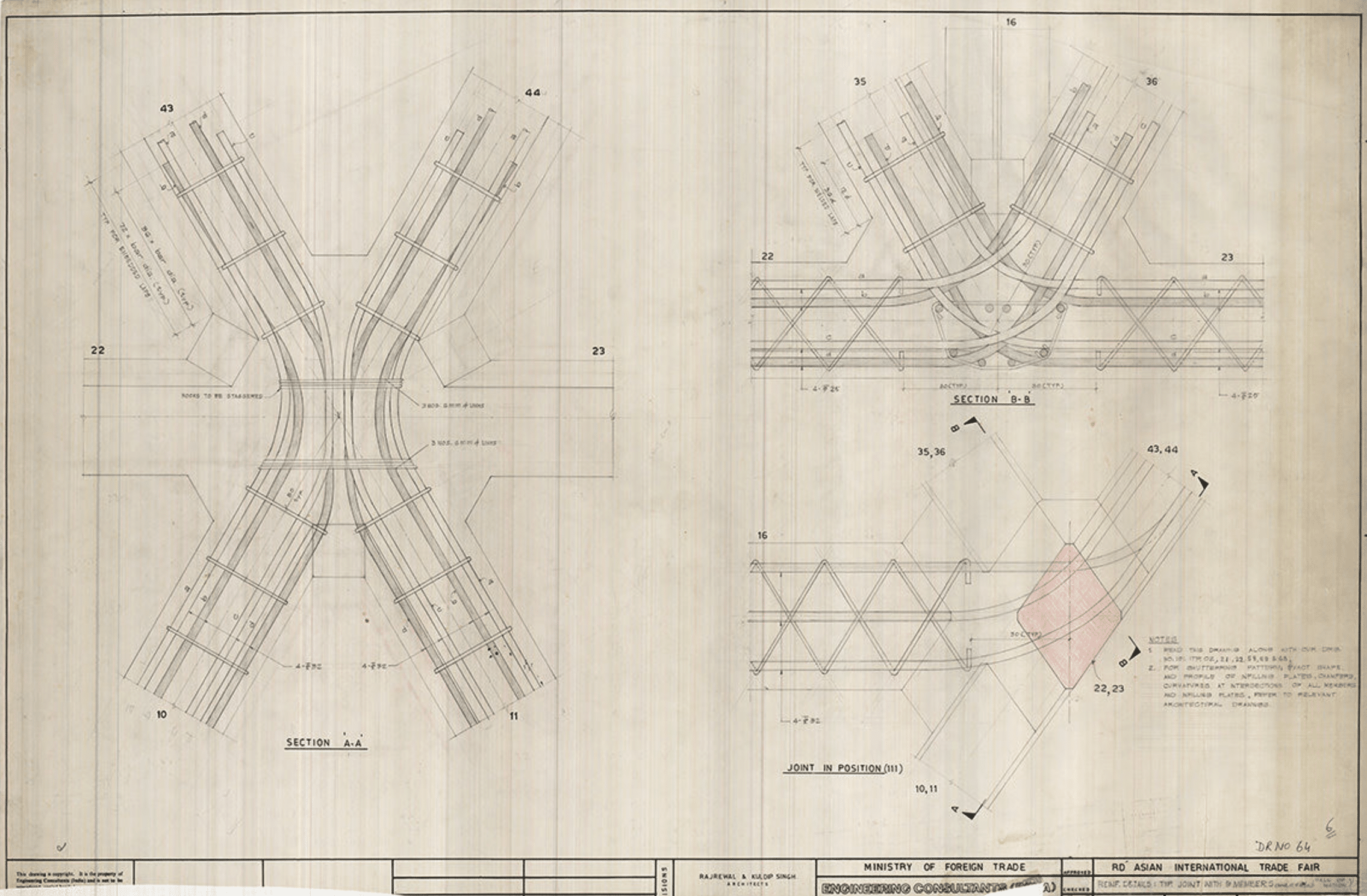
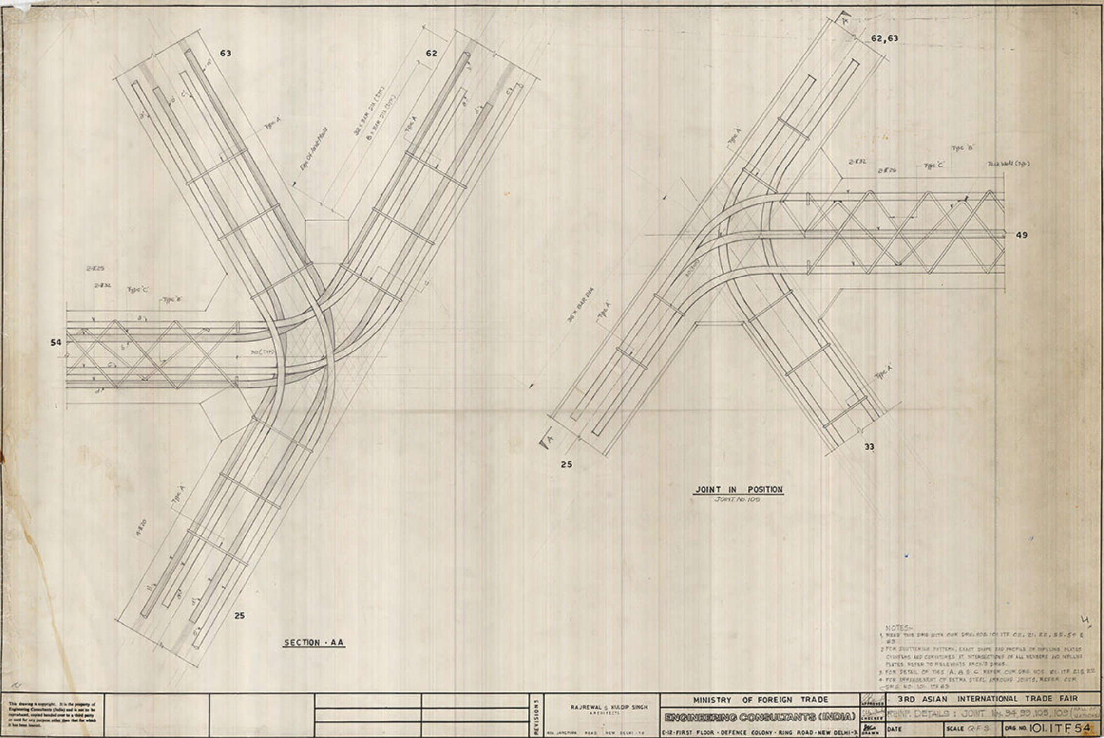
Despite having scrupulously detailed the joint reinforcing geometry, a note on the drawings permits the contractor to make adjustments but stipulates that a physical model must be produced. Note 4 on Sheet 101.ITF.55C reads: ‘The contractor shall make prototype model of typical joints showing the arrangement of reinforcement through the joints for approval by the engineer in charge before execution.’[20] Raj recognised that the resolution of these joints was crucial to the success of the project. While they appear to be fully resolved in his drawings, he knew it was important to involve the contractor in the process of planning for their fit-up. The elegance of the completed cast-in-place joints is remarkable and contributes to the slenderness of the final structures, which were tragically demolished in 2017. The legacy of these buildings, for their ingenuity and clever adaptation of standard construction methods, lives on.
Raj, Komendant, and Kawaguchi, all of roughly the same generation, operating in different cultural contexts, exhibit shared interests and value systems in their drawings that are echoed in their personal writings and reflections on their work. Each drawing set underscores the importance of establishing underlying geometry, graphically describing complex forms, dividing structure into comprehensible parts, and articulating the load path, yet their execution of these ambitions is surprisingly diverse. While the Yoyogi set examines large sections of the structure at a time, the Kimbell drawings rarely narrow or focus on a specific element and instead examine the building in large, sequential sections, and the Hall of Nations proceeds methodically through a series of different scales from the entire building to a single joint detail. In each case, the structure is fully articulated, but the approach is fundamentally different.
While it’s not obvious to what extent these engineers directly contributed to the drawings or relied on experienced draftspersons, the drawings make evident the expertise and knowledge cultivated within their engineering practices. The variation of graphic dialects within these drawing sets illustrates their role as vehicles for invention and exploration. Each of these engineers wields this malleable language with great skill and deftness to reveal attributes of their structures that are not necessarily discernible in their built execution, but evoke their design process and the way they work through everything from the resolution of the load path to the constructability of a certain detail. Their drawings reinforce the idea that this language is a nuanced form of creative and cultural expression that belies the rational purity with which it’s often associated.
Notes
- Lincoln Electric Company, How to read shop drawings: with special reference to welding and welding symbols. Welding symbols as standardised by the American Welding Society [1st ed.], (Cleveland: Lincoln Electric Company, 1961).
- Among others, see Robin Evans’ renowned essay ‘Translations from Drawing to Building’ (1986) for an important discussion of the linguistic operations of architectural drawings.
- See Ken Baynes and Francis Pugh, The Art of the Engineer (New York: The Overlook Press, 1981), 11.
- For a thorough account of such miscommunication between engineers from the United States and the United Kingdom involving the production of merchant freighters during World War II, see John K Brown, ‘Design Plans, Working Drawings, National Styles: Engineering Practice in Great Britain and the United States, 1775-1945’, in Technology and Culture, (April 2000).
- In California, for example, the 1933 Field Act mandated that all unreinforced masonry school buildings be retrofitted or rebuilt to improve their seismic resistance. The significance of this ruling incentivized engineers in California to rethink the way they made drawings and specifications. Some of the engineers from this time period, who were pioneers in seismic design practice, directly attribute the Field Act to the superiority and rigour of drawings produced by California offices as compared with other American practitioners. See John Meehan, interview by Stanley Scott in Connections: EERI Oral History Series, (vol 25, 2017).
- For a useful discussion of the role of drawing in the professionalisation of engineering, see John K Brown, ‘Design Plans, Working Drawings, National Styles: Engineering Practice in Great Britain and the United States, 1775-1945’, in Technology and Culture, (April 2000).
- Mamoru Kawaguchi, ‘The Design of Structures—From Hard to Soft’ in Seven Structural Engineers: The Felix Candela Lectures, ed. by Guy Nordenson, (New York: The Museum of Modern Art, 2008) 105.
- Ibid, 106.
- For two excellent essays on this topic see John Ochsendorf, ‘Architecture and Engineering Education’, in Structured Lineages: Learning from Japanese Structural Design, ed. Guy Nordenson (New York: The Museum of Modern Art, 2019) and Seng Kuan, ‘Introduction: Tange’s Yoyogi, World’s Yoyogi’, in A+U (no 588, 2019).
- For a useful discussion of piece drawings see John K Brown, ‘When Machines Became Gray and Drawings Black and White: William Sellers and the Rationalization of Mechanical Engineering’, in The Journal of the Society for Industrial Archeology, (Vol. 25, No. 2, 1999) and Steven Lubar, ‘Representation and Power’, in Technology and Culture, (Vol. 36, No. 2, 1995).
- For model images, see Mamoru Kawaguchi, Structure and Sensibility: Principles and Methods of Structural Design (Tokyo: Kajima Institute Publishing, 2015).
- This sequence of events is described in detail in August E. Komendant, ‘Kimbell Art Museum Fort Worth, Texas 1967-72’, in 18 Years with Architect Louis I. Kahn (Englewood: Aloray, 1975), 115-131.
- See Guy Nordenson, ‘The Lineage of Structure and the Kimbell Art Museum’, in Lotus International 98, 28-48.
- Komendant, 18 Years with Architect Louis I. Kahn, 1975.
- Ibid, 122.
- Ibid.
- See Mahendra Raj’s essay ‘My Initiation into Structural Engineering’, in The Structure: Works of Mahendra Raj, ed. by Vandini Mehta, Rohit Mehendiratta and Ariel Huber (Zurich: Park Books, 2016), 22-35.
- See Mahendra Raj, ‘Hall of Nations & Halls of Industries: Large Exhibition Hall Complex | A Case Study’, in The Structure: Works of Mahendra Raj, ed Vandini Mehta, Rohit Mehendiratta and Ariel Huber (Zurich: Park Books, 2016), 142-151.
- For a description of the site work involved, see Raj, ‘Hall of Nations & Halls of Industries: Large Exhibition Hall Complex | A Case Study’, in The Structure, 2016.
- See Note 4 on Sheet 101.ITF.55C dated October 11, 1971 in The Structure, 2016.
Gina Morrow is an Associate Partner at Guy Nordenson and Associates, a New York City-based structural engineering firm.
