Brunel’s Camera Lucida: A Closer Look
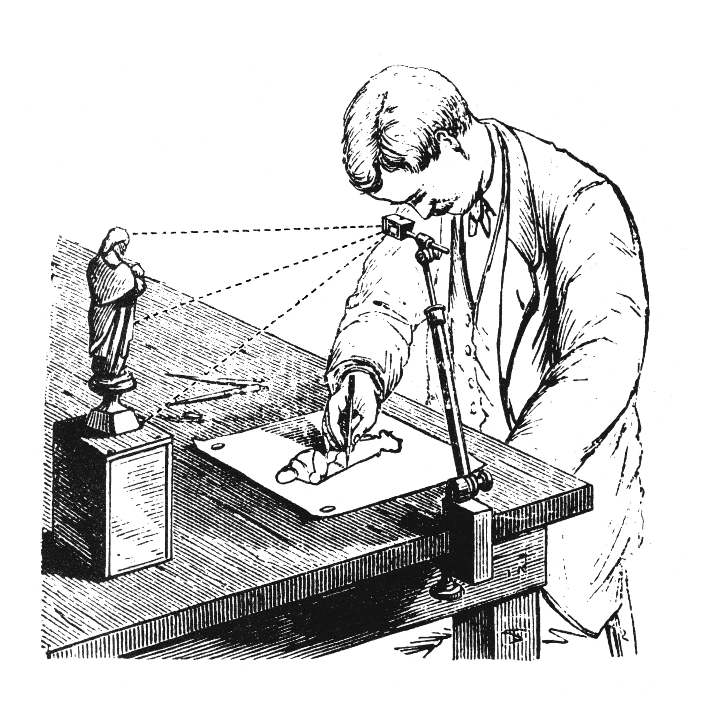
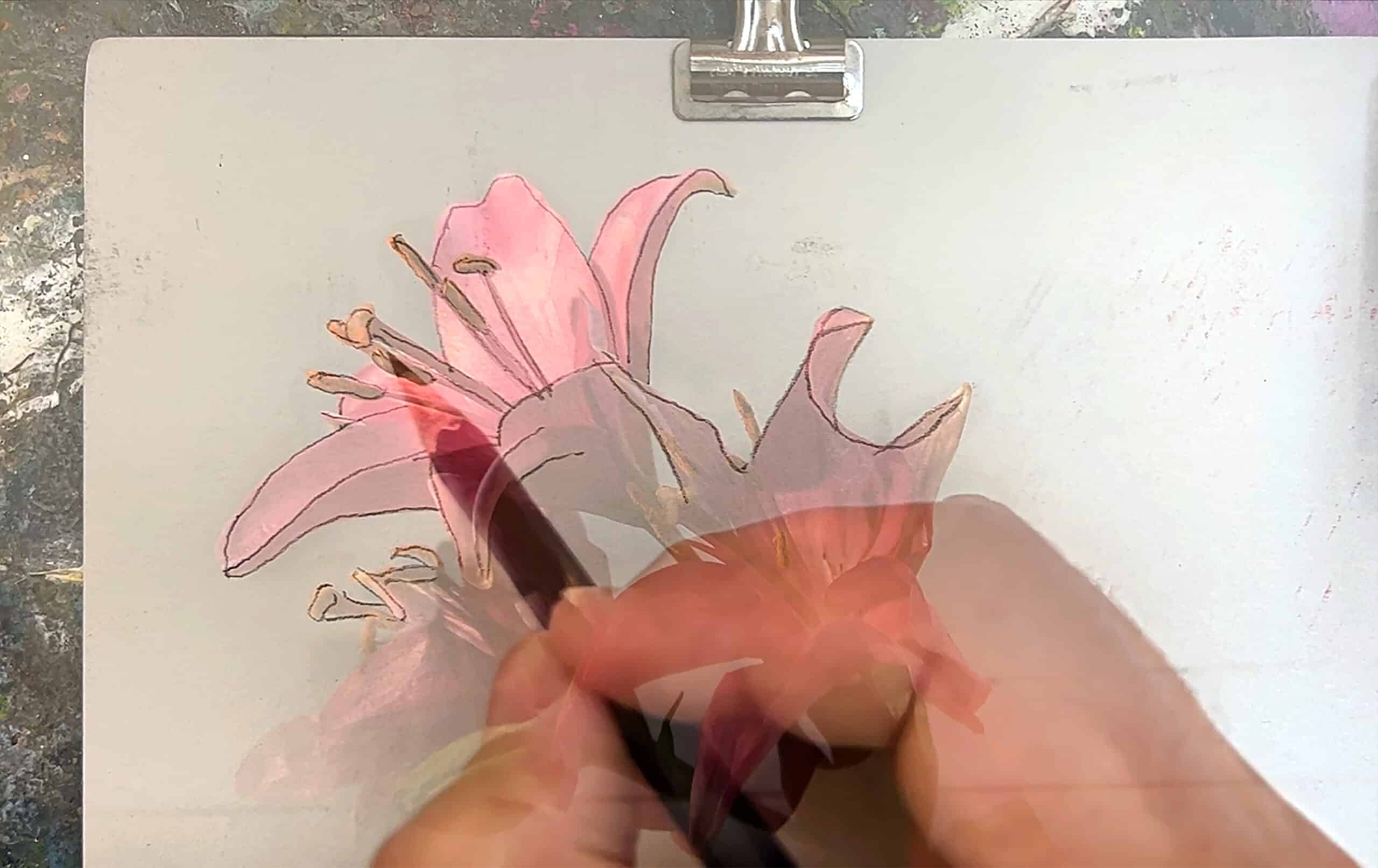
A camera lucida is a 19th-century drawing aid. When you look into the eyepiece, you see a ghost image of your subject overlaid onto your paper. Since you can see your hand holding your pencil with your subject superimposed, you can trace directly from real life. Invented in 1807, before photographic processes were invented, the camera lucida was used by artists, scientists, architects, and engineers to produce accurate stills from life.
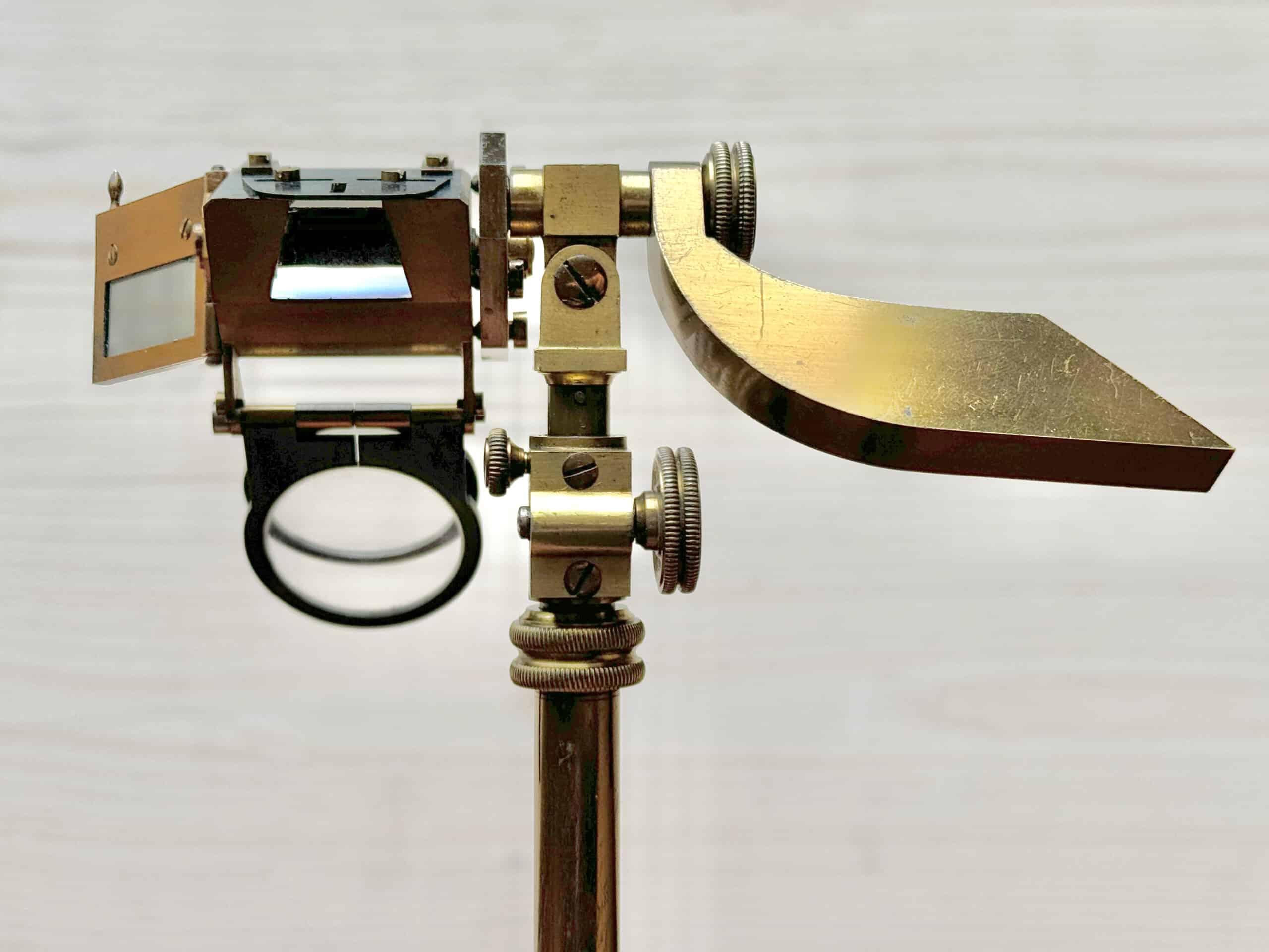
The camera lucida in the Drawing Matter collections is a unique specimen. Not only was it owned by Isambard Kingdom Brunel,[1] but drawings in his sketchbooks at the University of Bristol Brunel Archive suggest he designed this model himself.[2] I have studied camera lucidas for fifteen years and amassed an extensive research collection of the devices from the 1820s to the late 20th century. There is no camera lucida in any collection, catalogue, patent archive, or literature like it.[3]
This essay tells three design stories-speculations based on a close examination of Brunel’s device and sketchbooks: the what, the why, and the how of Brunel’s camera lucida. I will first summarise its features, performance and user experience compared to a typical camera lucida. [4] I will then ask ‘why did Brunel make it?—what does the user experience reveal about Brunel’s motivations for designing a new camera lucida? Lastly, I will offer a forensic reading of Brunel’s notes that displays an iterative discovery process and the detours that refined his vision for a new camera lucida. For these stories-speculations, I rely on close analysis of the camera lucida and close readings of the available sketches and notes, as I piece together a narrative about a singular creative mind attacking a design idea from sketch to production.
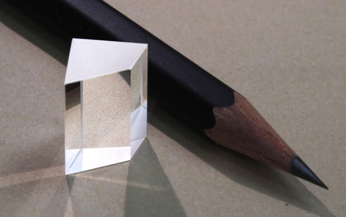
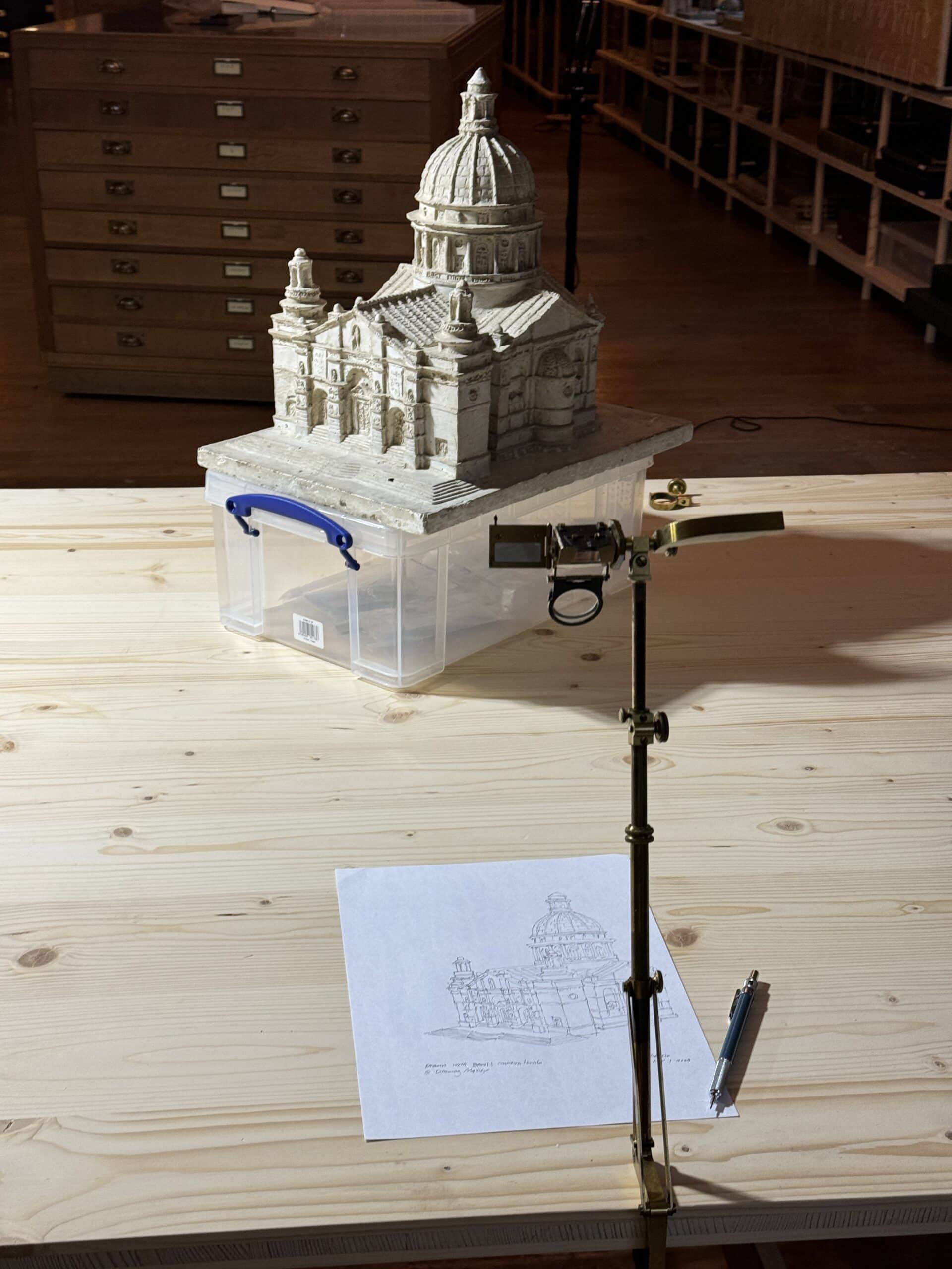
To understand Brunel’s design, let us start with an examination of how a camera lucida works. A camera lucida uses a small prism as a beam splitter. When you look at the exposed edge of the prism, the lower part of your vision looks directly at your paper below. The upper half of your view is diverted into the prism, and through internal reflections, you see your subject in front of you. Because you are looking very closely, within 1-2cm, the boundary between the two views is a soft, feathered overlap, combining to make it look like the view ahead is superimposed over your paper below.
There are different prism designs, but the original optical system, first made by English chemist William Hyde Wollaston (1766-1828), uses a quadrilateral cross-section:
The prism is encased in a housing atop a telescoping arm attached to a clamp. Affix the camera lucida to a table and position the eyepiece above your paper with your subject in front of you. The height of the eyepiece determines the size of the ghost image. Raising the prism makes the translucent subject image appear larger on the page, producing a larger drawing. Unlike a photographic camera lens, where light vectors converge and diverge, producing different focal lengths with curvilinear deformations, the camera lucida prism reflects light in straight, undistorted paths. The view in the camera lucida prism is the same as your natural visual field. If you position the eyepiece above your paper equidistant between the eyepiece and your subject, your drawing will be a perfect one-to-one scale drawing. Doubling the distance between the prism and paper makes a drawing twice the scale of the subject; doubling the distance between the prism and the subject yields a drawing at one-half size.
Story 1: The Brunel Camera Lucida, what is it?
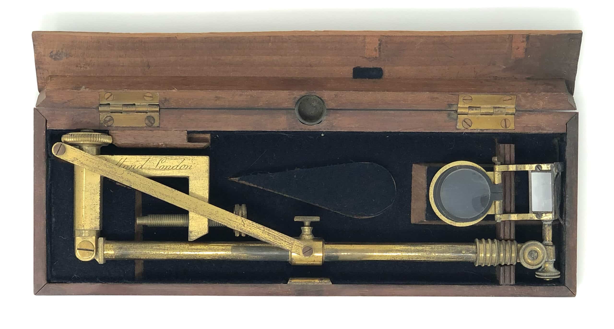
By the time Brunel outlined camera lucida designs in his 1858 sketchbook, the camera lucida had been in production for a half-century.[5] The standard design had not changed much in that span; different designers created accessories or added features to stand apart, but they were nearly all Wollaston prisms mounted on a telescoping stand.[6] At first glance, Brunel’s device in the Drawing Matter collections does not differ much from the Wollaston camera lucida and its variants made throughout the first half of the 1800s. It has a table clamp with a hinged telescoping arm. The arm supports a brass housing containing the prism, a pair of swinging lenses to adjust focal variances, an adjustable narrow viewing slot, and a hinged shader that pivots in front of the eyepiece to reduce bright subjects.
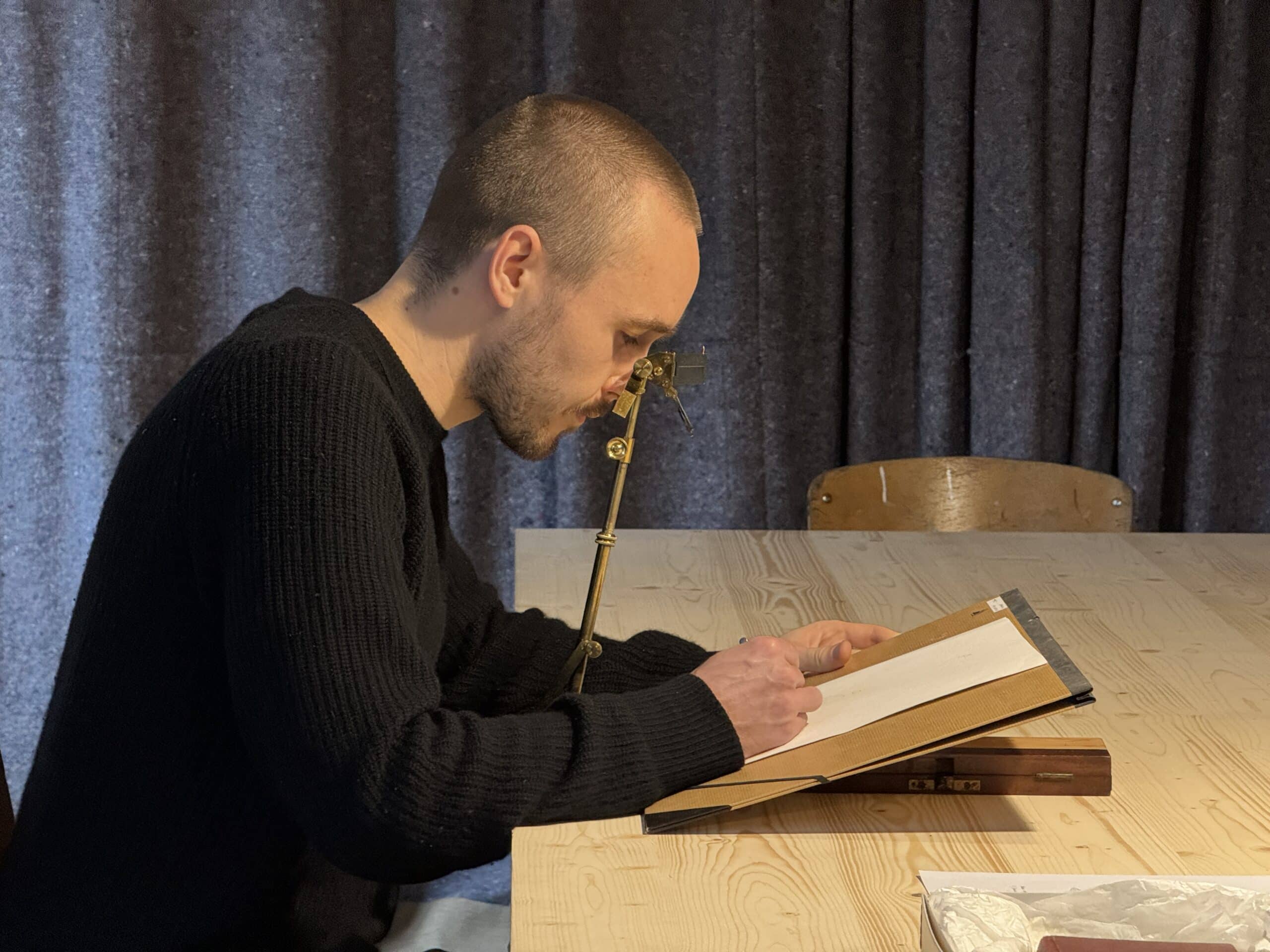
A Wollaston prism produces a beautiful, crisp, translucent image, but if you don’t place your eye very close to and directly above the prism edge, you won’t see it. Since the prism viewing window is small, with an opening only one centimetre wide, you must keep your head very still as you draw. Slight movements can make you lose the ghostly overlap of the subject image and your drawing hand. Stabilizing your head floating 2cm directly above a small eyepiece can literally be a pain in the neck. To produce larger drawings, you must raise the eyepiece higher, forcing you to stand while drawing. Depending on your height and the height of the prism, you may be straining your back to get your eye above the eyepiece.
Brunel’s prism geometry makes a small but significant change to the Wollaston optics. He alters the top surface of the prism, angling it down 20º from the horizontal orientation of the Wollaston geometry. He maintains the primary obtuse angle at 145º and the bottom angle at 75º just as they are in a Wollaston scheme.[7]
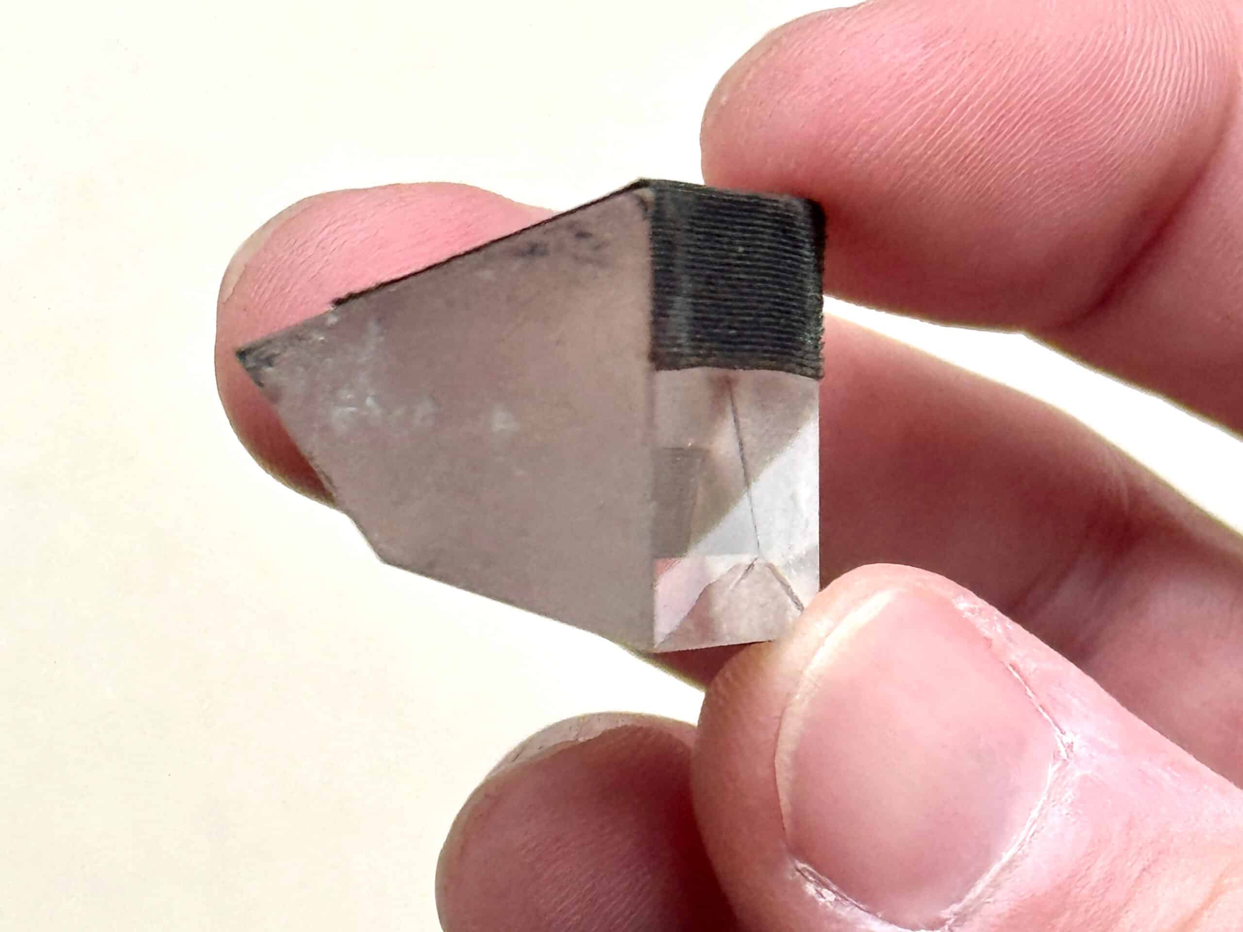
By changing this prism surface angle, Brunel also changed the user viewing angle. A camera lucida’s internal reflections work when the eye is perpendicular to the top prism plane. Wollaston’s prism has a horizontal top surface positioned parallel to a flat table below. The user must place their eye at 90º to the prism—and their paper—to see the ghost image. By lowering the top surface angle by 20º Brunel shifts the viewing angle by 20º from vertical. Instead of being perpendicular to the table, the user must position their eye at 70º. This dramatically improves posture while drawing.
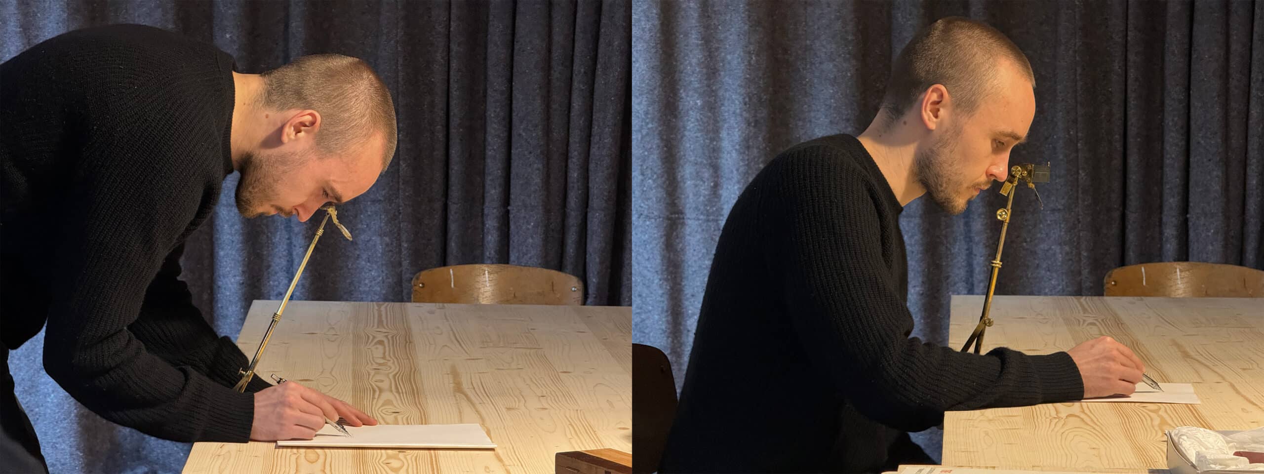
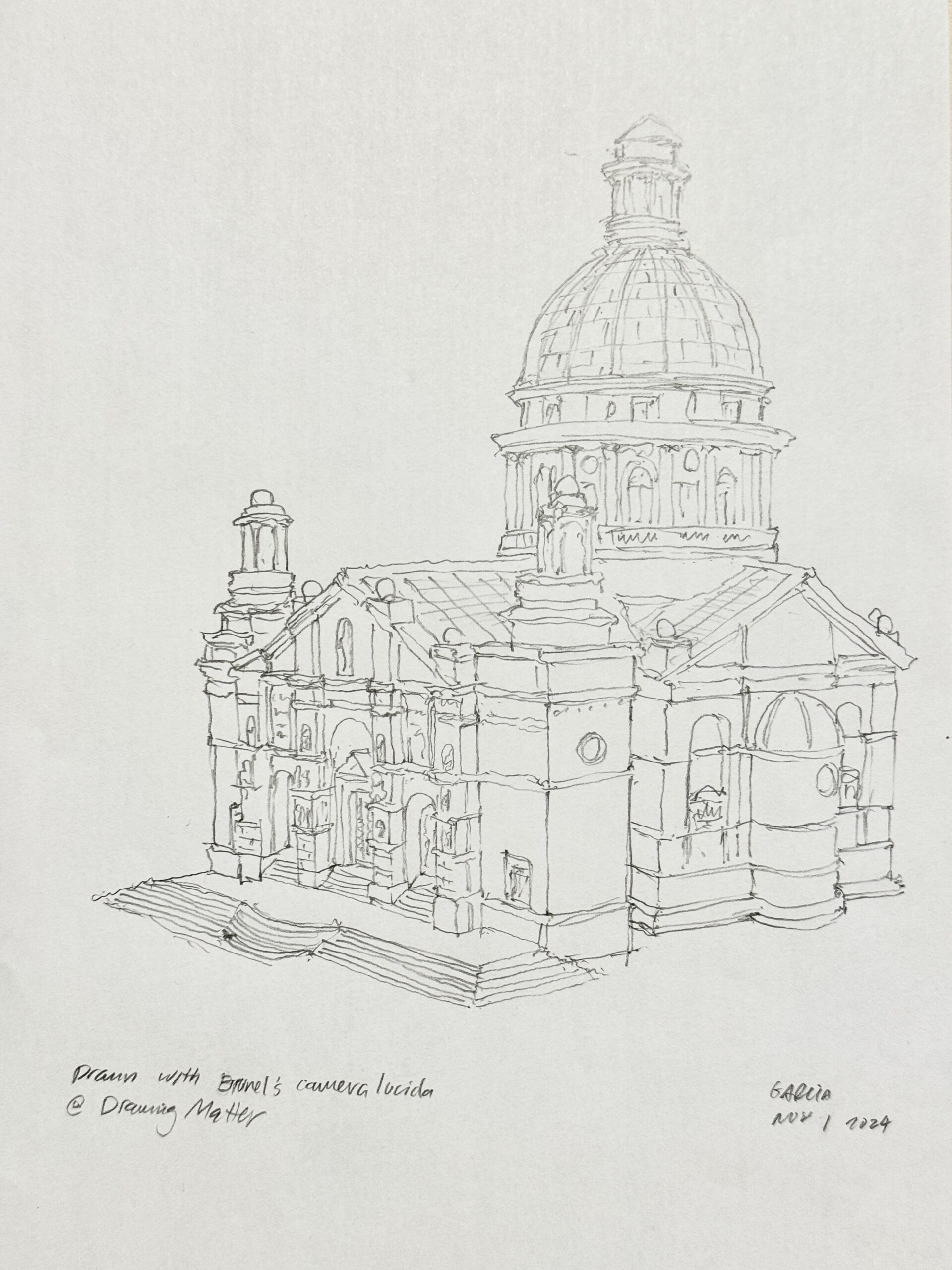
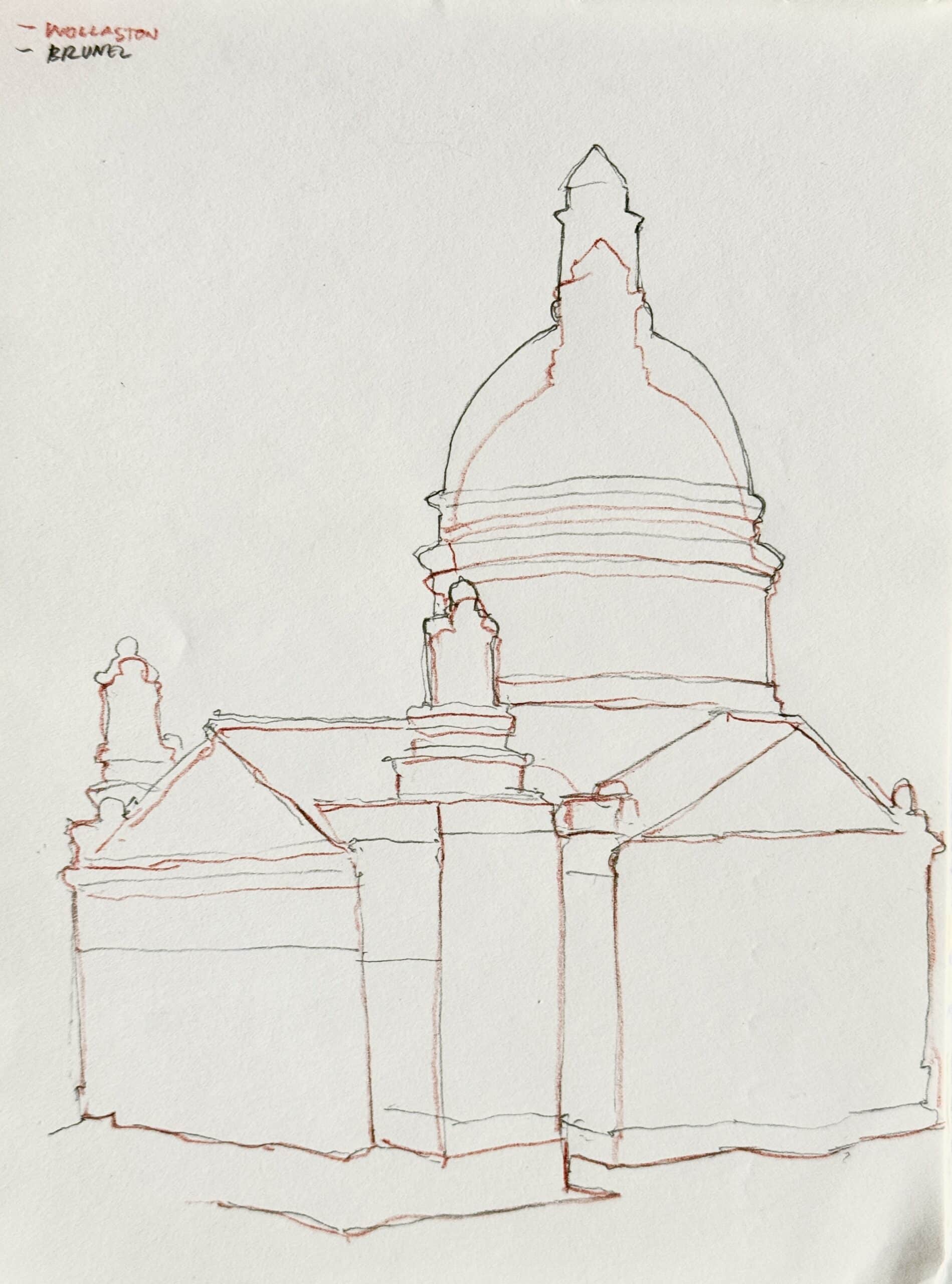
Like a Wollaston prism, Brunel’s optics are sharp and bright. I could make a nice ten-minute drawing of a plaster model while seated; to make this drawing with the Wollaston, I would have been required to stand. After I completed the drawing, I recognized a critical flaw in Brunel’s design. The ghost image was crisp, but the drawing was vertically elongated. I placed the Wollaston camera lucida eyepiece precisely where I had positioned the Brunel device to confirm that the Brunel prism vertically stretched the projection. I made an overlapping set of drawings to check the apparent discrepancy. The 20º angle shift, while better for the neck and back, creates a ghost image that isn’t perpendicular to the page, skewing the image, much like a video projection thrown on an angled wall. The only solution to this problem is to make an angled drawing surface to maintain perpendicularity with the viewing angle.
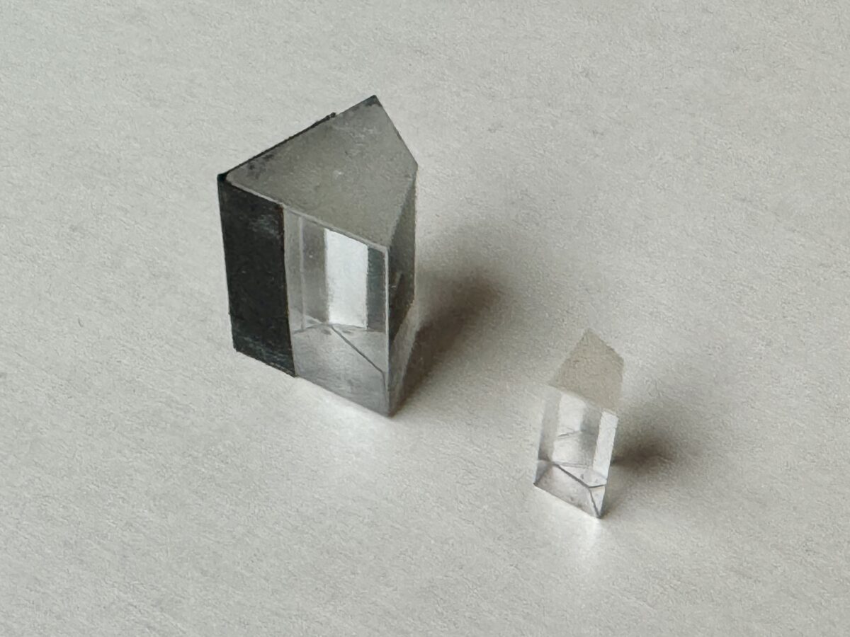
Brunel’s prism is enormous. It doubles the edge lengths of a standard Wollaston; it uses eight times the amount of glass. A bigger prism does not make the ghost image larger or brighter. Raising the eyepiece enlarges the superimposed view, no matter the size of the prism. The amount of light that enters the prism increases, but the viewing slot is no bigger than a typical Wollaston eyepiece; any additional light that enters the prism is negated by the narrow viewing opening.
Camera lucidas often came with an accessory to further narrow the viewing slot. Reducing the size of the exposed prism edge provided two benefits. By shrinking the visible prism area, the user dims the ghost image’s brightness. In daylight, the superimposed view may overpower a dimmer paper, preventing the user from seeing their hand. The smaller slot balances the light for easier drawing.
To draw accurately, the overlay image must maintain registration. If it drifts or the eyepiece moves, the image will cease to align with the drawing. A narrower slot improves image-drawing correspondence. A curious feature of the Wollaston prism is that the ghost image does not drift in the page’s north-south direction but moves slightly east-west if the user shifts their eye by the tiniest amount. A smaller viewing slot increases precision in the viewer’s eye location, keeping the image in place from left to right.
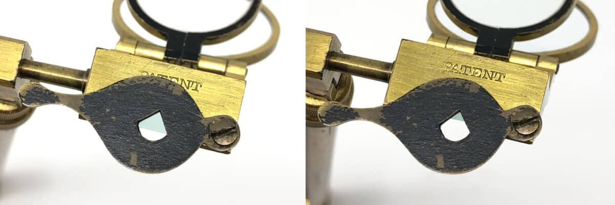
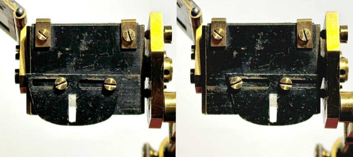
Brunel’s prism size modestly enlarges the horizontal viewing area, but this caused a problem.[8] A larger viewing width increases the alignment error at the edges. If Brunel placed a narrow slot to prevent eye drift, the widened extremities would not be visible, nullifying any benefit of the larger prism. To solve this, Brunel made a sliding slot. This adjustable slot allows the user to slide it to the edges and improve ghost image alignment across the wider projection on the page.[9]
The solid brass form opposite the eyepiece is a curious shape. The form suits an early 20th-century abstract sculpture more than a mid-Victorian engineering tool. There is no other camera lucida with this element. At first, I thought it might be a stabilizer for the eye, giving a user’s cheek a resting place. Tests proved this armature, no matter its position, does not align with the face in a way that would improve eye placement. While drawing, however, it did work as a handle to subtly adjust the eyepiece location.
Just as the sliding viewing slot expands the ghost image’s X-axis, a prism rotation extends the Y-axis. After setting up a drawing, gently using the handle to pivot the eyepiece tilts the eyepiece up and down, showing more above and below the initial field of view.[10] The calibrated horizontal and vertical expansion combination would have allowed Brunel to expand the drawing size, if only by a little, beyond the scale at maximum telescope extension.
Brunel’s larger eyepiece is very heavy. It sits on a pivoting mount at the top of the telescoping arm and requires a counterweight. I suspect the solid brass handle also became the necessary balancing agent. It provides a good handle to position the eyepiece, but its weight suggests its primary function is to stabilize the heavy eyepiece. Removing the piece from the assembly immediately caused the eyepiece to fall over. I speculate its form was spontaneously shaped from a larger piece as Brunel (or his fabricator) sought an appropriate counterbalance weight.
Story 2: Why did Brunel make it?
Why did Brunel design a camera lucida? He is a titan of 19th-century civil engineering, responsible for ambitious projects; he shaped modern England with steamships, bridges, tunnels, and railways. Perhaps there was ‘no project too small’ for Brunel, and attention to refining a small optical tool was on par with building the Great Western Railway. I speculate his redesign providing a new user experience was a personal accommodation.
Using a Wollaston camera lucida would have given Brunel two problems. At only 5 feet tall, Brunel would have had to stand erect to reach the eyepiece at even a low prism height.[11] Brunel designed his camera lucida when he was 52 and suffering from nephritis (Bright’s disease), a kidney condition that typically causes pain in the lower abdomen and back. Using a Wollaston camera lucida may have been, at best, inconvenient. At worst, it may have caused significant discomfort. Brunel examined his user interface problem and came up with an effective solution: he changed the prism. His new geometry would have allowed a shorter user with lower back pains to use a camera lucida effectively at different eyepiece heights. It is a new user experience suited to Brunel’s physical limitations.
In September 1858, Brunel came home from Switzerland with chronic pain. His doctor diagnosed his kidney affliction and prescribed a trip to Egypt for relaxation and a warm climate.[12] He reluctantly departed for Alexandria in early December.[13] Brunel’s Large Sketchbook 2, Folio 37, titled ‘Camera Lucida’ is dated Sept 7, 1858 contains technical drawings and notes depicting camera lucida variations.[14] Brunel may have used a camera lucida before this, but his attention to the assembly and design of camera lucidas at this date suggests an interest in developing a tool for his Egyptian sojourn.
Henry Marc Brunel’s diary entry of December 30, 1858, at the Temple of Dendera confirms that his father brought a camera lucida to Egypt, saying, ‘Here my father got out his camera lucida & stand to make a sketch…’[15] His entry refers to a camera lucida and stand. To draw en plein air, a camera lucida requires a stable portable surface to draw. Typical outdoor drawing tables looked like the one below made by Charles Chevalier.
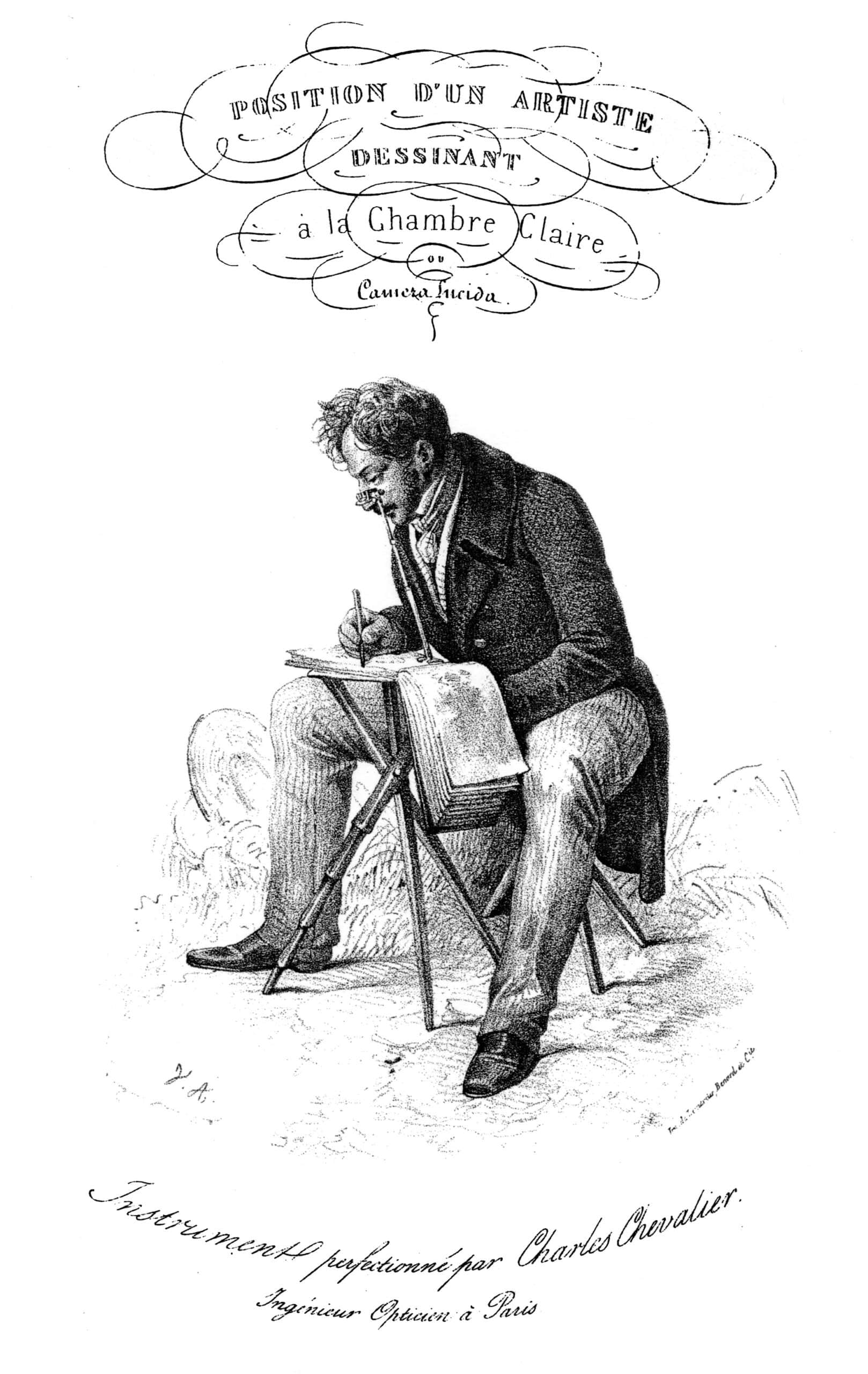
The seated artist here is making a small sketch. The eyepiece is low; the sketchbook appears to be smaller than A4. This table has telescoping legs, suggesting it can rise to standing height, but it would not be stable enough at standing height to keep a camera lucida ghost image still enough to draw. It also has a flat table with no way to tilt it to the 20º angle Brunel’s camera lucida optics required.
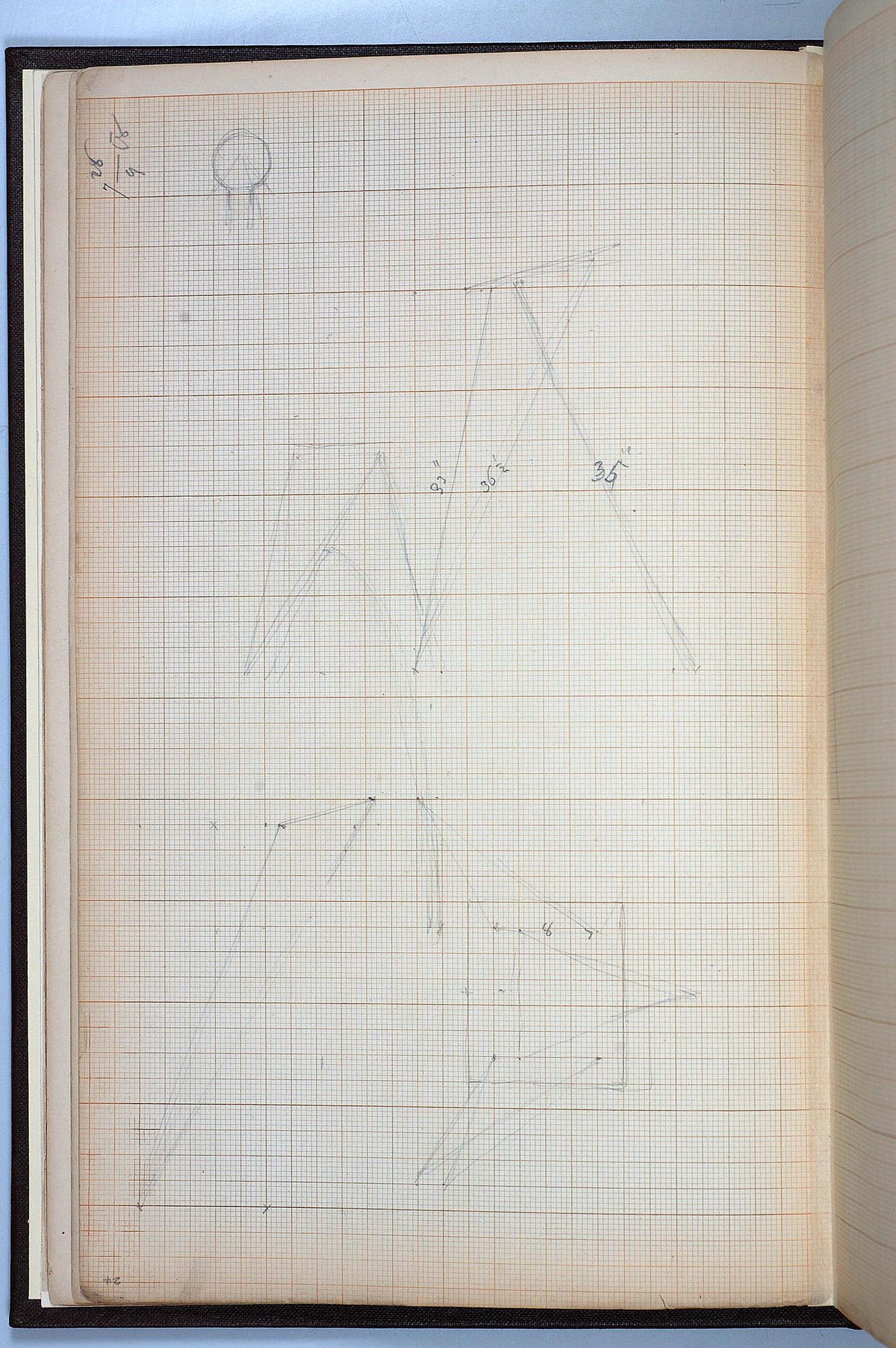
On Folio 38 of the large sketchbook,[18] Brunel writes—somewhat illegibly—a section on a proposed drawing table ‘As to table — [I stand?] and an angle of 20º to 25º.’[19] Below this, Brunel writes ‘As to size — for all [ordinary?] sketching out of doors, 14 x 12 or 15 x 13 [inches] is quite sufficient…’[20] There is a single number in the lower sketch on Folio 16 of Small Sketchbook 32 outlining the dimension of a short triangle side as ‘8.’ If this is the top edge of the triangular leg as seen from below, and this drawing is to scale on the grid, then the surrounding rectangle is 12 x 14. This is the drawing board, sized to fit the largest drawing Brunel can feasibly make.
He continues, ‘Make a table for sitting at [illegible] about 9” above [illegible] for me and for standing at and making larger drawings.’[21] The remaining text is difficult to decipher, but it appears that Brunel was specifying his needs and lamenting that commercial offerings did not meet his requirements of a larger table that maintains a 20º angled surface and can adjust the height between standing and sitting positions. A truly versatile camera lucida table would accommodate both a standing and sitting user and adjustable eyepiece heights for different drawing sizes. I imagine Brunel envisioned a matrix of possibilities: standing and drawing large, sitting and drawing at a medium size, and sitting to draw small sketches. I believe his notes outline the first iterations of a custom camera lucida table.
Looking at the small sketchbook drawing, these dimensions place the front of the table surface at approximately 32 inches (81cm) high. The maximum height of the eyepiece—the farthest the telescoping tube of the Brunel model will extend to make the largest drawing possible—is about 19 inches (48cm) above the table or 51 inches (130cm) off the floor. At 60 inches (152cm) tall, Brunel’s eye level would have been around 54” to 55” (137-139cm), providing him with a comfortable standing posture to be slightly above the prism height and peer into the prism at the requisite 70º angle. If he were to sit on his 19-inch (48cm) seat (outlined in the small sketchbook next to the standing table), he could produce a small camera lucida drawing by lowering the eyepiece to the minimum height of 9 inches (23cm) or lower the table further by splaying the triangular legs.[22] From this position, he could sit and extend the eyepiece higher. His table design is the necessary complement to his camera lucida; it accommodates different drawing sizes while maintaining the required 20º drawing surface angle.[23]
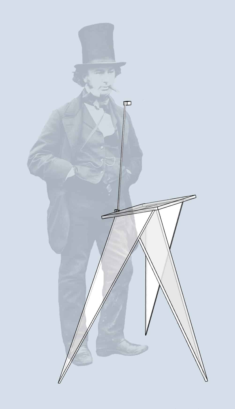
This duo of bespoke designs—a camera lucida and a portable table—is Brunel’s travel drawing kit. I posit that his diagnosis and prescribed travel inspired Brunel to draw the marvels of Ancient Egypt with a tool designed for precise renderings. Dissatisfied with the existing camera lucidas, the brilliant engineer made his own suited to his needs.
Story 3: How did Brunel arrive at the final design?
Among the sketches in Brunel’s Large Sketchbook 2, Folio 37 is the star of the show.[24] Its drawings are delicate, precise, and comprehensive. We see the full orthographic representation of a camera lucida eyepiece at the bottom—top, side, and front. The upper left shows a clamp, and the upper right drawing is a telescoping arm and the eyepiece represented below at half the scale. This is a complete picture of a camera lucida design.
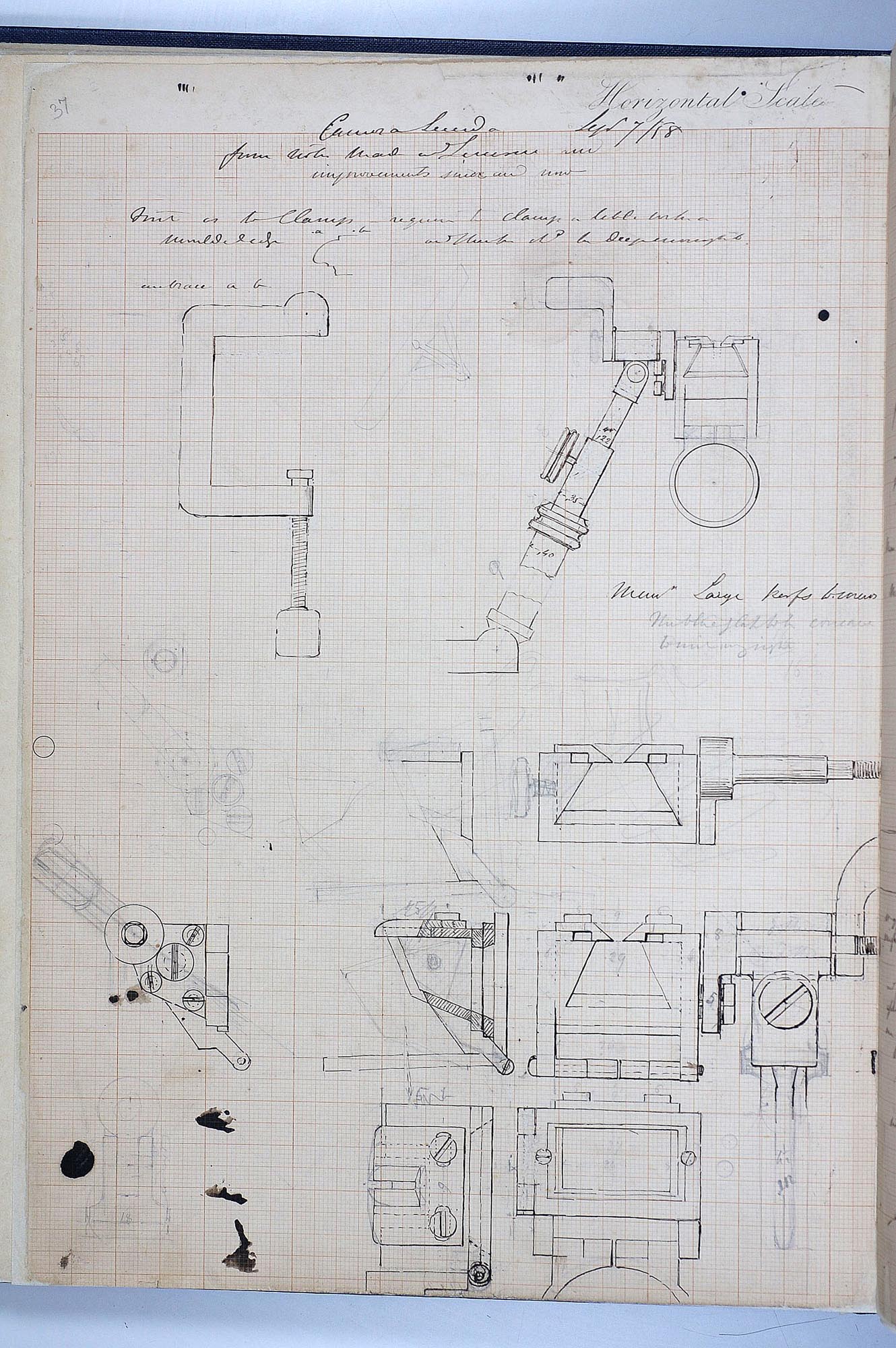
The drawings, however, do not depict the camera lucida in the Drawing Matter collections. Most notably, the eyepiece Brunel details is a Wollaston prism. It has a horizontal top surface, not the 20º angle change that allows him to sit while drawing.
There are other discrepancies. The narrow viewing slot has a bevelled opening, positioning the viewing slot directly against the prism. Its design allows it to slide horizontally, but much less than the final production model. The front shading window is shorter; the glass covers the entire prism instead of the lower half. His clamp stamped ‘Troughton & Simms, London,’ differs from the one he delineates in the top left. So when did Brunel change the design? How do we read these drawings as a layered, iterative map of his refinement process? My hypothesis: Brunel came across a camera lucida during his stay in Switzerland and began sketching small, user-friendly modifications. Upon returning to England, he advanced the first schemes into a more accessible user experience, intending to use it in Egypt. With time running out and a new brief for a personal, portable device, Brunel made some compromises to his original vision, resulting in the specimen in the Drawing Matter collections. Let’s take a tour around Large Sketchbook 2, Folios 36-38, to see the designer at work.
Folio 37, title ‘Camera Lucida’ is subtitled, ‘from [notes?] made [at?] Lucerne.’[25] Next to this, in what appears to be different, lighter ink, Brunel writes, ‘…and improvements [since?] and now [or “new”].’ The first lines are about the clamp, saying ‘[first?] as to Clamp – require to clamp a table with a moulded edge…’ and draws a small cross-section diagram with ‘. a’ and ‘. b’ across the top. The dots indicate the dimension from the edge of the moulding to a depth sufficient for the clamp to be securely affixed. The clamp drawing appears to be a direct tracing of an existing clamp, not a measured design sketch.[26] Above it, the note appears to say, ‘[embrace?] a b,’[27] indicating that a new clamp design should accommodate thicker tabletops with deep mouldings.[28]
Brunel, trying a camera lucida in Switzerland, may have had trouble clamping to a thick table, or, predicting this problem in future use, notes that any good clamp design should accommodate different table edges. In either case, this is a demonstration of Brunel’s design mind: recognize a flaw and seek solutions.
The upper right drawing is a typical camera lucida unit with an added feature. Brunel draws the counterweight in the final model but with a different shape. It is smaller and rectangular. Looking closely at the smudged erasures, Brunel shortened the design after an initial sketch. I suspect this was the intended rotation handle design before discovering the need for a counterweight.
The first enlarged drawings immediately below match the handle drawing eyepiece at twice the scale. The following rows of drawings at the bottom of the page, however, expand the prism by 30%. The handle also grows, perhaps indicating that Brunel was planning for the extra prism weight.
The initial design is complete. The brief: 1) enlarge the clamp to fit more table edges, 2) expand the ghost image range by enlarging the prism, and 3) add precision adjustment mechanisms to calibrate the larger projection. But this design does not match the final design in two important ways. The eyepiece angle is different, and the clamp is not enlarged. What if these drawings were made before returning to England and receiving his diagnosis and forced holiday? Perhaps these first iterations were specifications that, if commercially produced, would provide an improved user experience but were not tested.
The Drawing Matter camera lucida acquisition also came with a standard camera lucida eyepiece, but it does not match the design drawn in the Lucerne pages. I posit the eyepiece belonged to the clamp-arm element supporting the Brunel optics. It is an off-the-shelf unit, made by Troughton & Simms for commercial sale, and repurposed for the Brunel prototype.
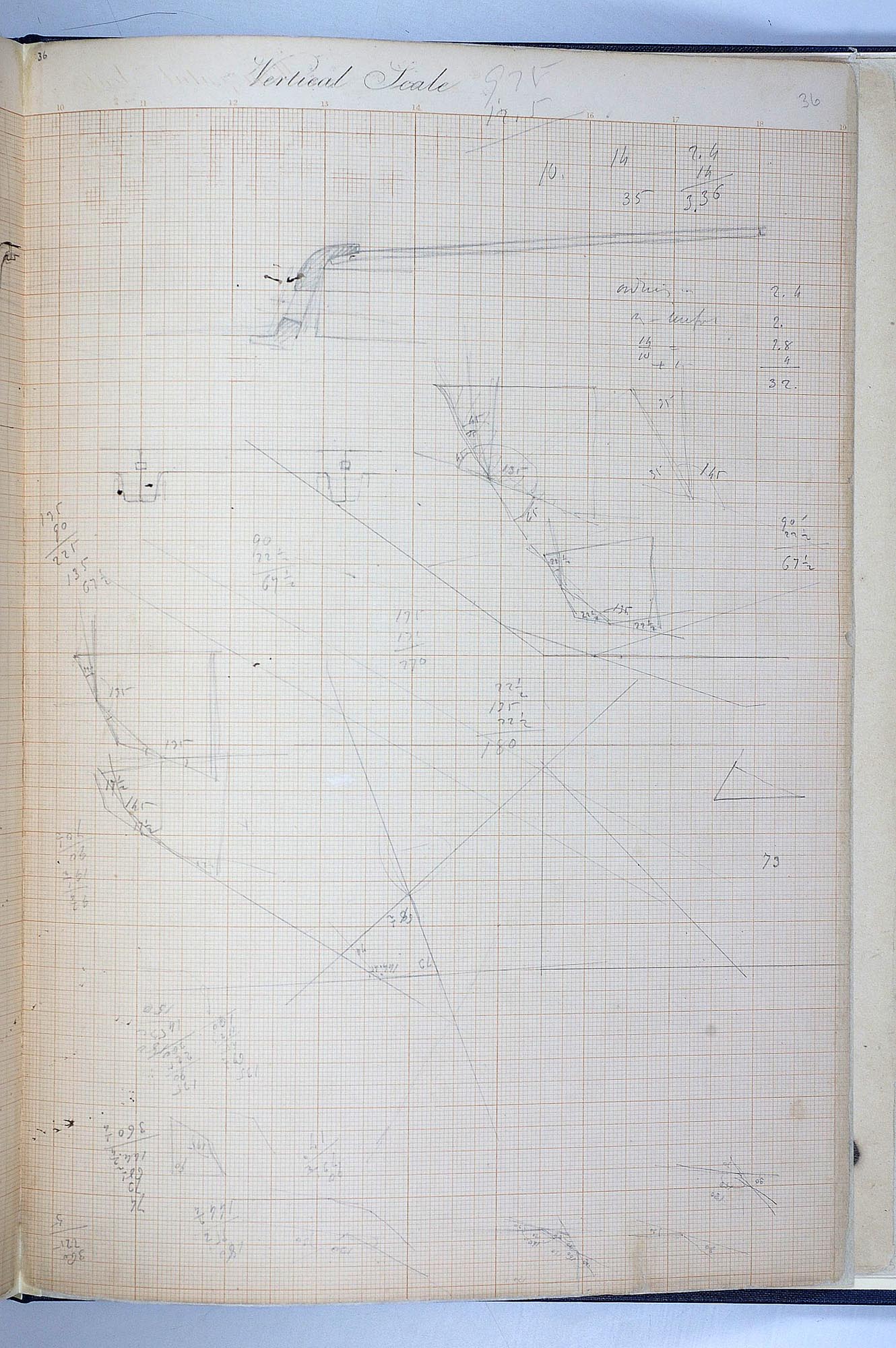
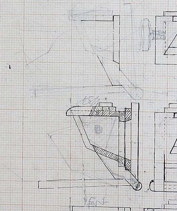
Back in London, Brunel scrutinizes the performance of this Troughton & Simms device in light of his intended travel drawing and makes further alterations. To save time, he adapts his eyepiece to the existing clamp and telescoping arm. He is designing a table, for his camera lucida, so he does not need to enlarge the clamp. He also reconsiders the optics. Trying a few sketches in Lucerne gave him ideas for improved performance, but with prolonged use, he reconsidered the optics. Folio 36, drawn entirely in pencil and littered with angle calculations, is Brunel’s study of prism variations as he searches for new, back-saving viewing angles.
In Folio 38, he draws, in pencil, the new prism design below an ink drawing of a Wollaston prism. This drawing locates the set screws seen in the final model, suggesting this is a later drawing as he prepares for the prototype. Folio 37 also has a faint pencil sketch of the new design superimposed on the eyepiece cross-section.
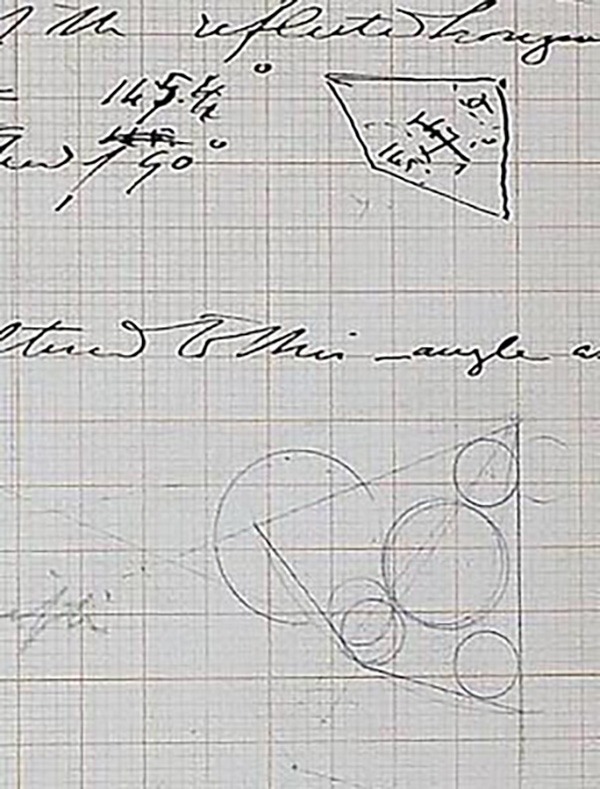
In a few short months, Brunel develops a new design for a camera lucida on the go in another country, goes back to the drawing board in London when he tests his ideas with focused energy, optimizes performance, while also abandoning previous goals, and produces a working prototype to test. It’s a charrette—a sustained, intense design project.
The design probably needed a few more iterations. The eyepiece is too big. The improved viewing area isn’t worth the massive prism. By my calculations, a prism 50% larger than a typical Wollaston would deliver similar results with Brunel’s sliding slot and pivot handle. The lower drawings on Folio 37 are not at an enlarged scale from the upper drawing, they show an eyepiece twice the size. He is moving quickly; It’s easy to double the size on gridded paper as a first attempt. If Brunel had time after his prototype, he may have reduced the prism size which would have also allowed him to calibrate a smaller counterweight. Instead, he compromises. Make a bigger counterweight and shave it down until it works. It does not matter if it’s an awkward shape. This is for his own use in Egypt.
I think Brunel also realized—too late—that his camera lucida needed more work. His son’s entire diary entry at the Temple of Dendera reads ‘Here my father got out his camera lucida & stand to make a sketch, but after a little time he found the camera was not quite in order, and therefore made a drawing of it without it.’
It may have been a failure for Brunel, an engineer renowned for his incredible successes as well as embarrassing defeats. Personally, I am grateful for this imperfect object. Not only does it expand the existing catalogue of optical drawing devices, but it also opens a window into the messy and complex process every designer experiences—even one of the most acclaimed engineers of all time.
Notes
- Provenance: Brunel Family, by descent. From the collection of autograph letters and other archive material belonging to a descendant of Brunel, sold at Christie’s South Kensington, 29 November 1996, lot 91.
- The University of Bristol Brunel Archive, Large Sketchbook 2, record number: DM162/8/1/1/Large Sketchbook 2/ and Small Sketchbook 32, record number: DM162/8/1/2/Small Sketchbook 32/. All images of his sketchbook images reproduced here are supplied by the Brunel Institute, a collaborative venture between the University of Bristol and the SS Great Britain Trust.
- John Hammond and Jill Austin’s The Camera Lucida in Art and Science (CRC Press, 1987) is an indispensable manual that catalogues the diverse designs and applications of camera lucidas.
- I was in residence at Drawing Matter as a Visiting Scholar and drew with Brunel’s device over three days: November 6-8, 2024.
- The University of Bristol Brunel Collection: DM162/8/1/1/Large Sketchbook 2.
- Artists, inventors, and mathematicians offered several significant alternatives to the Wollaston prism in the early 1800s. Giovanni Battista Amici’s 1818 system used a compound glass prism, and A. Alexander’s 1840 ‘Graphic Mirror’ employed partially silvered glass and a mirror to make the ghost image. British artist and inventor Cornelius Varley produced the ‘Patent Graphic Telescope,’ a camera lucida eyepiece fitted to a telescope in 1811 and a version for a microscope in 1840. Still, these were not commercially successful and remain rare in collections. See Hammond and Austin.
- Wollaston’s original prism had an obtuse angle of approximately 127º, but Wollaston prisms made by others throughout the 19th century varied between 130º and 145º. The angle discrepancies would not have affected optical performance; the differing angles would have corresponded to marginally different viewing angles. At the scale of a tiny prism, the change in viewing position amounts to fractions of millimetres between prisms of differing angles. See Hammond and Austin (Appendix). To verify this data, I have also measured over 30 different Wollaston prisms in various collections.
- I made pencil marks at the extreme sides of the ghost image and compared it to a Wollaston view. Brunel’s design yielded a wider view by approximately 10%.
- It helps reduce horizontal misalignment, but it does not completely solve the problem. Sliding the view is akin to an assembled panorama on a smartphone camera. The image is smoothly joined by moving the eye’s viewing location several millimetres from side to side but keeping the eye looking down and not pivoting the head to see the extremes. Tilting the head to see the edges increases the misalignment. Brunel’s solution does not completely eliminate a pivoting head.
- This image expansion, like the sliding viewing slot, has limitations. Rotations beyond approximately 10º alter the angles of the prism’s internal reflections and result in a compressed, distorted image.
- ‘Brunel was known for being visibly self-conscious about his height and would often wear very tall top hats to increase his height. He was 5 feet (1.52m) tall.’ <https://www.ice.org.uk/what-is-civil-engineering/meet-the-engineers/isambard-kingdom-brunel> [accessed 13 December 2024].
- Isambard Brunel, The Life of Isambard Kingdom Brunel, (London: Longmans, Green, and Co., 1870), 517.
- ‘He was very unwilling to be so long absent from England, especially as a new company had just been formed to finish the ‘Great Eastern’… However, it was thought that very serious consequences might follow if he remained at home; and in the beginning of December he left for Alexandria, with his wife and younger son.’ Brunel, The Life of Isambard Kingdom Brunel, 517.
- University of Bristol Brunel Archive DM162/8/1/2/Large Sketchbook 32/folio 37. I will follow the Brunel Archive nomenclature, calling each sketchbook sheet ‘Folio’ and the number corresponding to the page number.
- Diary of Marc Brunel, University of Bristol Archive DM1307/2.
- University of Bristol Brunel Archive DM162/8/1/2/Small Sketchbook 32/folio 16.
- DM162/8/1/2/Small Sketchbook 32, Folios 14 and 15.
- University of Bristol Brunel Archive DM162/8/1/2/Large Sketchbook 32/folio 38.
- Brunel’s handwriting, especially in his later years, is notoriously illegible. In 2019, researchers at the University College London and the University of Innsbruck developed an AI program to decipher Brunel’s letters, hoping a computer could succeed where humans have failed. To test the machine, they aptly transcribed a self-aware letter from Brunel saying, ‘Sir, In compliance with your request I send you rather a good specimen of some of the worse handwriting in England.’ <https://www.bbc.com/news/uk-england-bristol-49347472.> [accessed 13 December 2024]. As of this writing, I have not found access to this program nor to any transcription archives produced by this research effort. In email exchanges, the transcription team told me the model is not public; a high error rate prevents their work—the computer model or the few completed transcriptions—from being released. All transcriptions included in this article are based on my careful reading and contextual interpretations.
- Brunel does not specify units here, but these dimensions in inches (35 x 30 cm and 38 x 33 cm) are in keeping with standard camera lucidas. At full height—the farthest the telescoping tube will extend—most camera lucida ghost images will nearly fill an A3 sheet.
- ‘[illegible] stand from 2.[10?] [meaning 2’-10”, or 34”] to 3’.0 [illegible] the [seat?] to be 19” then [illegible] make the low table 2.4” — and the higher [illegible] 8” to 10” higher — a difference too great to obtain with the [illegible] of legs.’ The following paragraph begins, ‘My present idea as to [illegible] stand in…’ While the rest is illegible, it depicts a few small sketches and identifying ‘pair a & b’ relating to the small adjacent sketch, possibly referring to table legs. He concludes the page by saying, ‘with a tripod seat also.’
- See the above footnote, identifying ‘the [seat?] to be 19” then…’ Measuring the grid scale on the small sketchbook drawing, the seat height is approximately 18 inches (46cm), leading me to believe the ‘19’ in his notes refers to the seat height for the stool.
- The sketches are merely geometrical; there are no specifications for materials, thicknesses, or connections. To adjust this table, the three triangular legs would have to be hinged, but some intermediate struts may have been necessary to provide stability. It is also not clear if these are meant to be solid triangular panels of wood or bent metal triangular legs.
- University of Bristol Brunel Collection: DM162/8/1/1/Large Sketchbook 2/folio 37.
- Brunel was in Lucerne, Switzerland during his 1858 trip. Brunel, The Life of Isambard Kingdom Brunel, 516.
- A typical camera lucida clamp opening is between 1.5 and 2 inches (4-5cm). The scale of this sketch—measured by the paper grid—leads me to believe that he is tracing an existing clamp on a camera lucida he is using and not a scaled drawing of a larger design.
- I suspect the word is ‘embrace,’ meaning ‘encompass’ or ‘include.’
- I personally have had this problem. When using a vintage camera lucida, some tabletops are too thick.
Pablo Garcia is an Associate Professor at the School of the Art Institute of Chicago. His multidisciplinary research practice blends forgotten analogue methods with cutting-edge digital technology, paying homage to our long history of human-machine collaborations in art and design. Since 2013, Garcia has commercially produced the NeoLucida, a contemporary camera lucida. His extensive research into 600 years of drawing machines can be found at drawingmachines.org. Garcia has architecture degrees from Cornell and Princeton Universities.
