Notes on The Palace of the Assembly and Museum at Chandigarh
Drawing Matter was introduced to José Oubrerie by Stan Allen after publishing his text Just Begin in July 2020. Oubrerie worked for Le Corbusier on the Brazilian Pavillion at the Cité Universitaire in Paris in 1958 and in the Atelier at 35 Rue de Sèvres from 1959 to 1965. The following text is the first in a series of two transcriptions of informal email correspondence in which Oubrerie provides commentary on drawings for buildings in the Chandigarh Capitol complex that are now in the Drawing Matter collection.
The correspondence has been lightly edited.
18 July 2020
Dear Professor Oubrerie,
I wanted to send you images of two Chandigarh drawings that we have assembled here; this is in case you can throw any particular light on them, in terms of authorship, function or technique.
I would be very grateful for any thoughts you might have, on either of them.
With best wishes, and with thanks again – and in advance.
Niall Hobhouse
18 July 2020
Dear Niall,
Thanks for contacting me, you have a few of Le Corbusier drawings shown and I was pleasantly surprised that you had met my long-time friend Jullian [Guillermo Jullian de la Fuente] (we worked together from 1958 all the way long to 1965 at the Atelier and a little after until 1966 and remained connected until his death) and that you have now these 12 pages of a sketchbook about the Governor’s Palace (Euengio Tobito worked on this project with Le Corbusier) that probably Le Corbusier gave Jullian when he asked him to develop the project designated to replace it: the Knowledge Museum. The Governor’s Palace had been rejected by the Indian Government, I think being too reminiscent of the image of government as former British Vice-King centralised power, as I heard it from some Indian Architects. Curiously they were looking to build it now… for its architectural value.
I have looked at the two drawings that you sent to me:
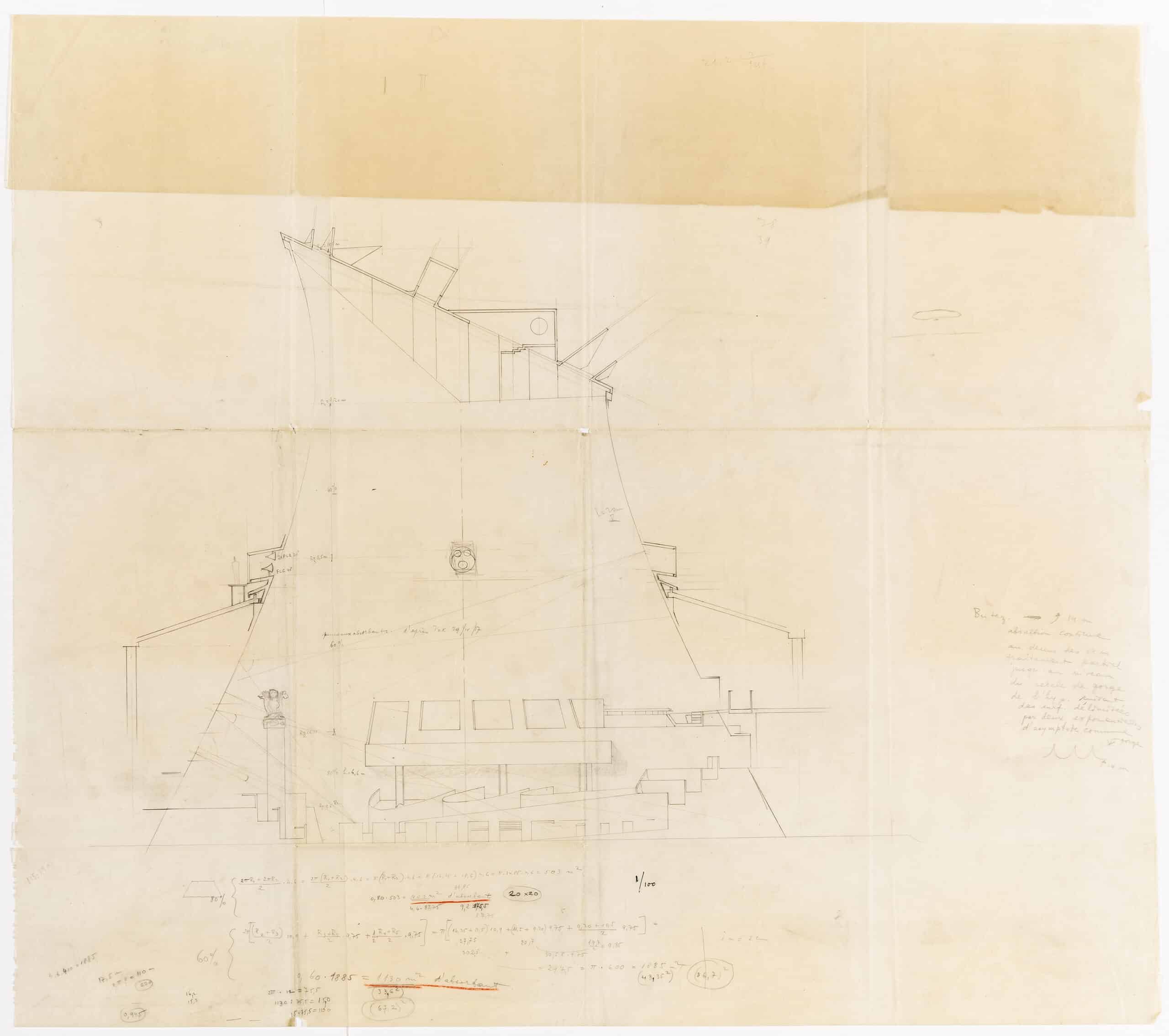
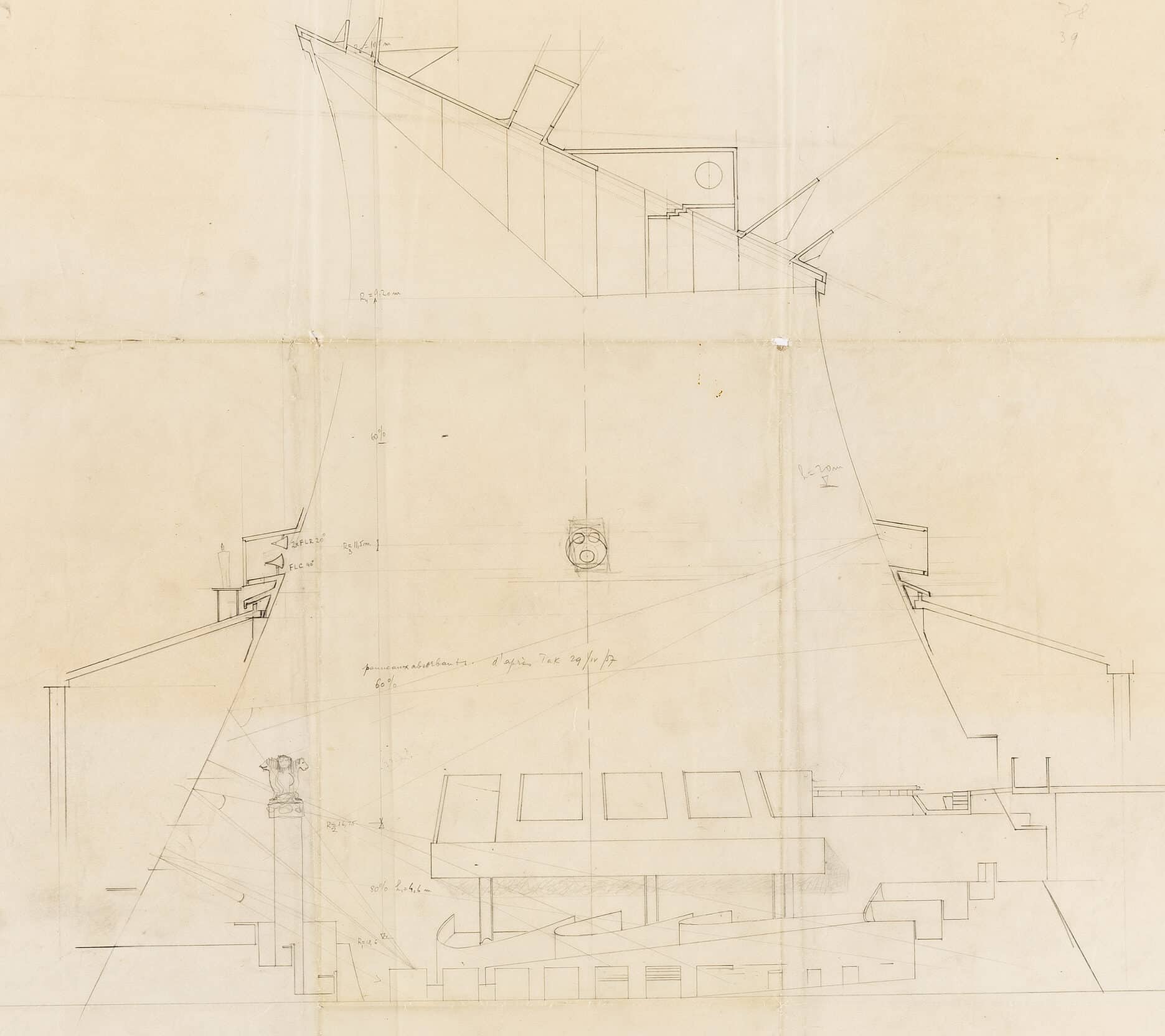
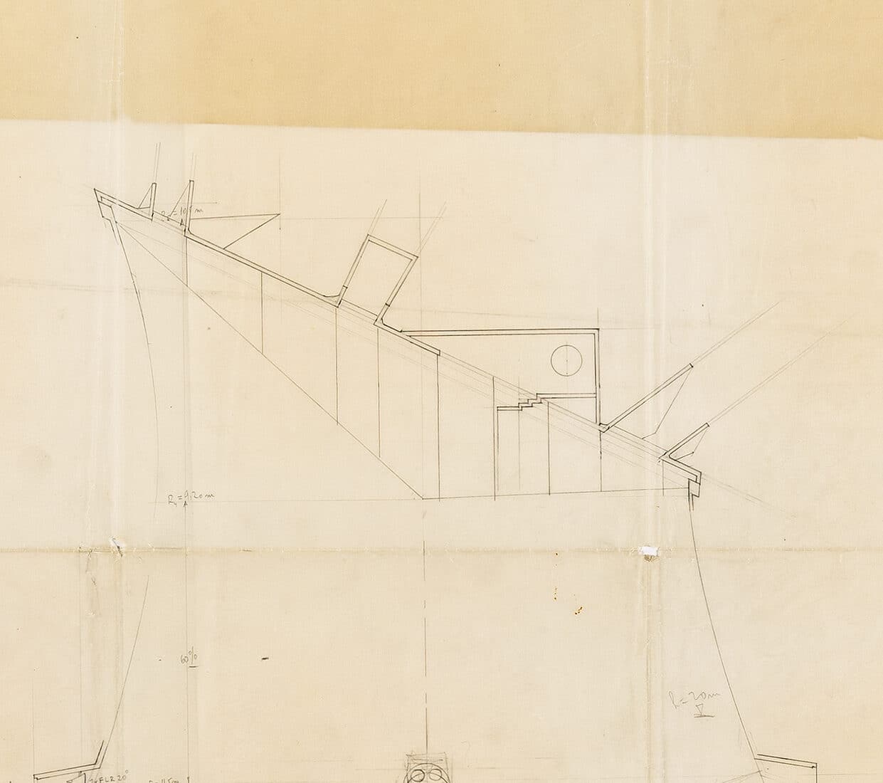
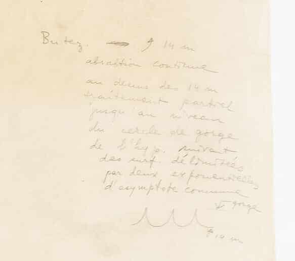
‘Butez / absortion continue au-dessus des 14m traitement partiel jusqu’au niveau du cercle de gorge de l’hyp. suivant des surfaces délimitées par deux exponentielles d’asymptote commune.’
‘Butez / absorption continues above 14m partial treatment up to the level of the throat of the hyperboloid, following the bounded surfaces by two exponentials of common asymptotes.’
The first is a section of the Main Meeting Room in the Assembly Building. It is a print as I see it from the photograph. It concerns the acoustics of the room which, being a hyperboloid of revolution, geometrically, is not very good for acoustics… repetitive regular reflexion of the sound, echos, etc… and the reinforced concrete material is not very helpful too…
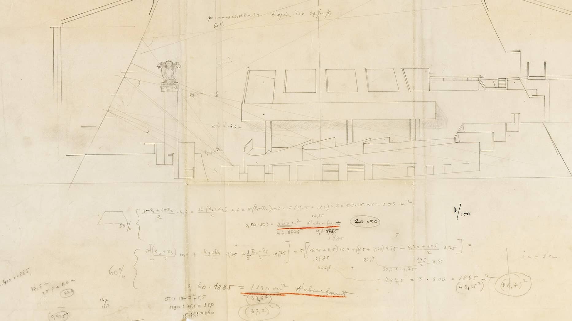
You can see the adopted solution in the photos of the interiors of the Assembly Chamber; absorbing ‘Clouds’ on all the periphery. You have at the bottom of your drawing calculations concerning the definition of percentages of absorbing surface necessary to obtain satisfactory Acoustics. Very probably the original drawing could be from the hand of Iannis Xenakis who was the atelier designer responsible for the project. (See the drawing in Le Corbusier Le Grand, page 500.)
The building was built between 1951 and 1962 but this drawing was probably from 1957, I suppose, it refers to information given by Mr Tak on 29/11/57, he was the Philips Acoustical engineer. This reinforces my conviction that it is from Xenakis as beginning of August. Le Corbusier was pressuring Xenakis to send him the drawings of the ‘Bouchon’ (the ‘cork’), i.e. the precise design of all the closure of the top of the paraboloid, a complex set of elements designed in relationship to the movements of the sun in Chandigarh which Xenakis had proposed and calculated.
At the end of August ‘59: Xenakis, Maisonnier and Tobito – the 3 actual collaborators of L-C – were fired … we were in the studio on 1 September, I think…
I have a sample of Xenakis’s handwriting, and I am pretty sure that your drawings are from his hand, but you would have to ask to a serious graphologue for confirmation after the original drawing.
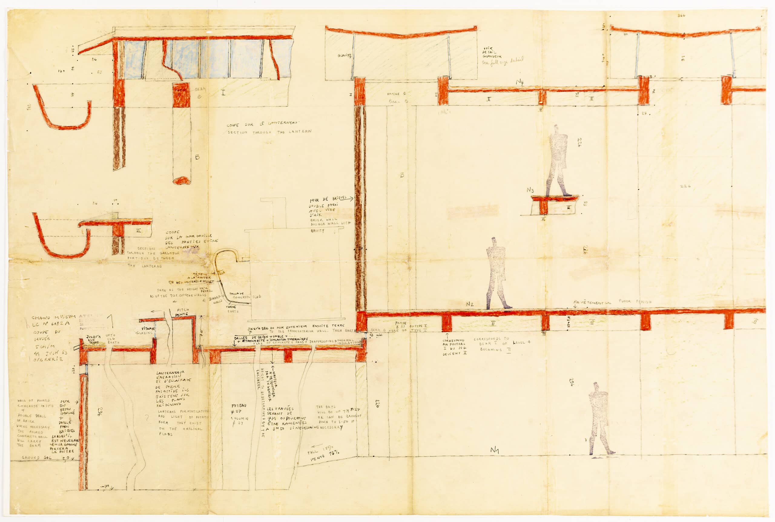
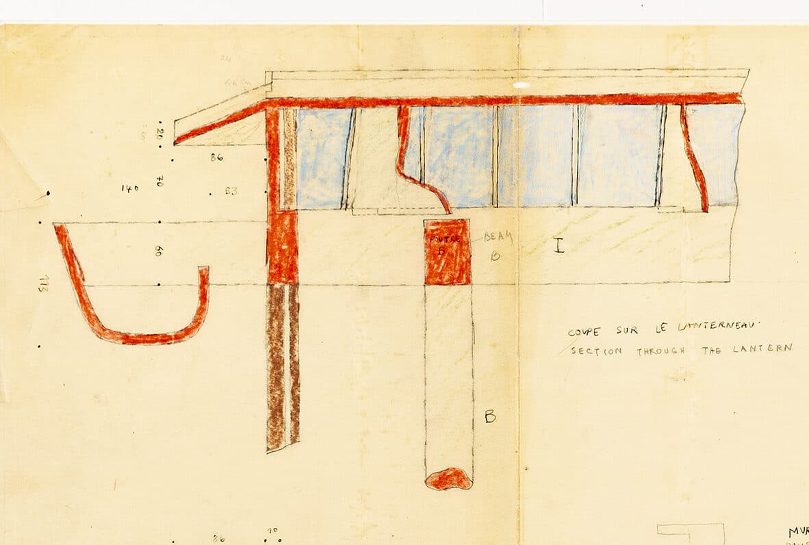
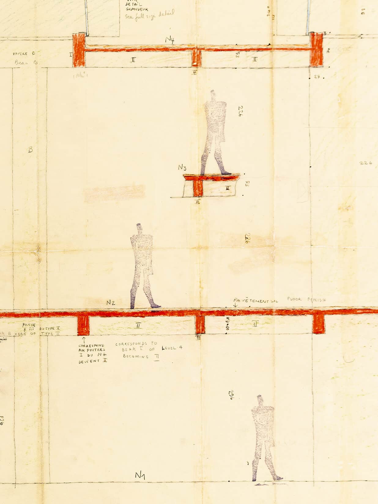
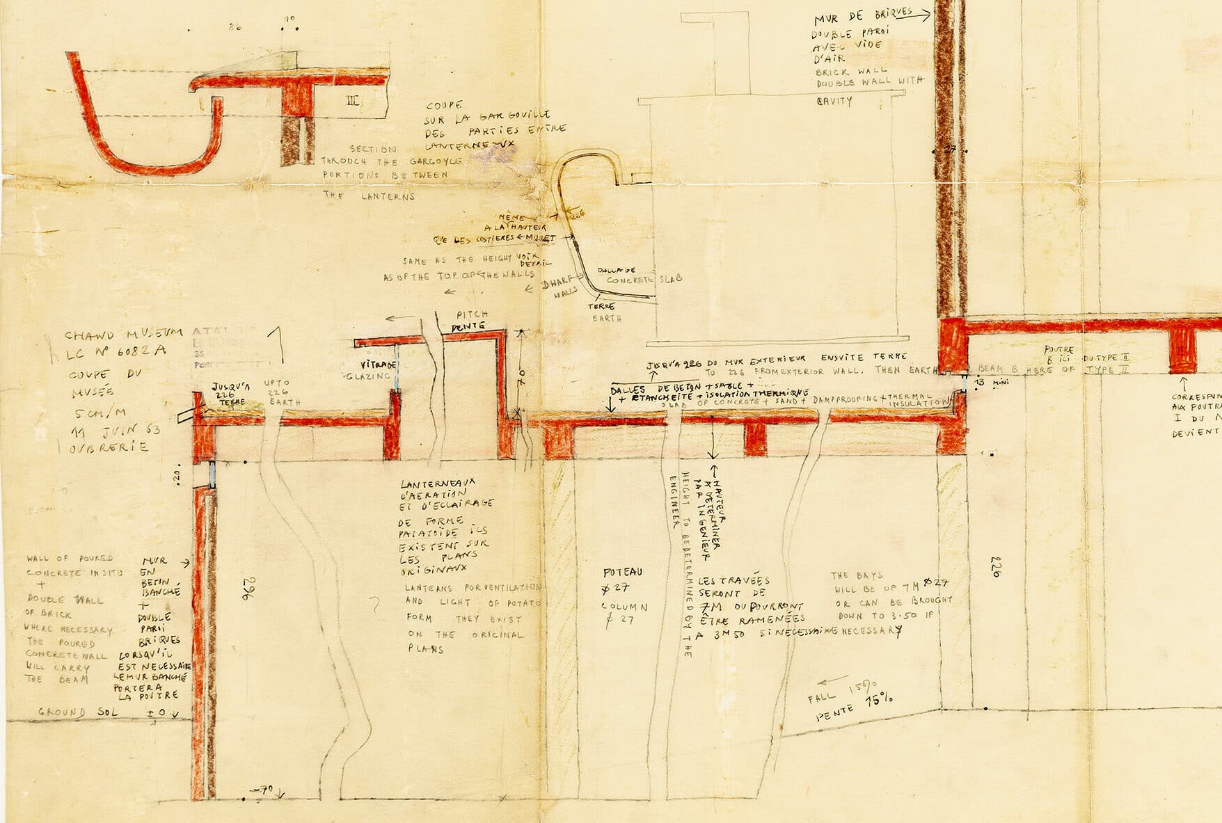
The second drawing is also a print (difficult for me to know from the photo but I think that it has been coloured after printing which otherwise would have turned the red to a more brownish tone). It is showing the dimensioning adopted for the section of beams and slabs of concrete, the nature of the facade walls etc… of the Chandigarh Museum. This drawing was made in Chandigarh, in Pierre Jeanneret’s Office as he was the Site Architect for Le Corbusier. The Indian Government was paying in rupees, so this was making possible to spend the money which was sufficient in India and L-C asked to Pierre, his cousin, to run the things there when they started construction.
Generally, for all the important buildings, the first stages of conception and preliminary drawings were made in Paris and L-C would take them to be developed in India where he was going one or two times a year for one month each. So, Le Corbusier put me in charge of designing the original project of the Museum in Paris and took the drawings with him to India. This explains also that while in India they were not drawing everything as usual for them in the inch/foot system but here all the dimensions are in metric, mostly according to the Modulor, and that all the texts are bilingual, French and English. They had to draw in the inch/foot system for the execution drawings.
It is a typical section showing the main Museum structure and its connection with the lower annexe construction as you see it at the bottom left of the drawing.
I hope that these explanations will help you, so you can say for the Palace of the Assembly building: Study of Acoustics, probably 1957 or beginning 1958. Print of a drawing probably by Iannis Xenakis; and for the other one: Chandigarh Museum, structural studies attributed to Pierre Jeanneret office, print and colour pencil I designed the project in 1964 or 65. I have to check so this drawing might be at the same date, the last trip of L-C may have been Fall 64… I will check and let you know this weekend at the latest Monday…
Bravo for your collection, great to have this interest in reinforcing the importance of Architecture as primarily an Art… I remain at your disposal for any other question and will send you what I find about dates etc…
Regards… Jose Oubrerie
3 August 2020
Dear Jose,
Thank you for looking so hard, and any detailed comments that develop from your studies will be greedily consumed at this end; what you have said is fascinating already.
Incidentally, we looked carefully with a conservator at the Museum and the Assembly sheets and are as certain as we can be that both of these are drawings. In any case, we would be fascinated to understand more of working practices in Chandigarh, and particularly communication between Paris and the site office.
Niall, very best
3 August 2020
Dear Niall
Don’t apologise, what you said is good news. The only test is exposure to solar or artificial light to see if they change colour, which can confirm what you think, but is dangerous for the drawings… The problem today is that we don’t use anymore the same type of machines and paper so few people know about it unless they are an old architect like myself.
I have been a little late because of other engagements but I am quite ready now I have just to pack up everything and answer also your new questions but I have to read Doshi’s paper and Stan’s one.
I am sure that Doshi’s work with L-C was different from the way we were working because this was always transforming, in fact a research as much as the projects themselves and you can follow this evolution over the succession of projects of L-C during his life…
I cannot get back to you before this Tuesday but I will be sending you by mail things by the end of the day…Thanks for your patience, Amicalement… Jose O
In response
From an email to the Drawing Matter editors from Luis Burriel Bielza, May 2021.
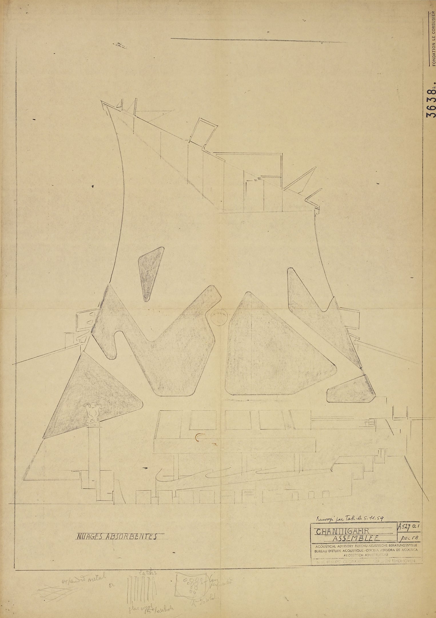
The drawing you own, other than of course helping to define the upper section of the Assembly Chamber (regarding canon lights), was used as a basic layout where different acoustic options could be tested with tracing paper. Among these solutions, we could find the floating ‘acoustic clouds’ included in the built version, with changing shapes, whose geometry always respected the minimal absorbing surface determined by Xenakis. Please find enclosed one of these options, a drawing currently held at the FLC under CHAN03638A (dated 05.11.1959). As Oubrerie explains, all calculations were finally verified by M. Tak, engineer from Philips. When Xenakis was fired in 1959, M. Tak continued helping out LC, taking care of the acoustic problems appearing in different projects (which arrived very often…). La Tourette and Firminy churches were part of them, even though due to their restrained budget, no final solution was given.
Your drawing is dated ‘d’après Tak 29/11/57’. As you see, things could take a long time to be developed in LC’s office! The second one I am sending you is from 1959, and the final solution (either light or acoustic devices) would be changed even once more in the built project, around 1962.