Re-presenting the Rococo
Johann Michael Fischer’s church of St Michael at Berg am Laim
In October 2017, I travelled to the outskirts of Munich to spend three days in the company of Johann Michael Fischer’s church of St Michael at Berg am Laim with the purpose of presenting it in drawings and photographs. The trip was sponsored by the Drawing Matter Trust and was intended to act as a prototype to inform further such surveys of German rococo churches. St Michael is a key example of Fischer’s work and of the wider German rococo movement and there is no shortage of written and visual information available, at least in terms of quantity. At the start, therefore, this study was considered as an experiment in method and representation rather than research, I saw the exercise as a process of passively recording a building that has been recorded before. The results were intended to provide more, and better, information about the building, enriching what was already understood and presented. It became immediately apparent, however, that the process of measuring a building cannot be passive. It inevitably tells us things that other forms of investigation do not. I will let you judge for yourself whether the information resulting from this experiment is better but, significantly, it is different.
Existing representations of a complex art
I have long been both beguiled and fascinated by the rococo churches of southern Germany. Indeed, their ability to elicit concurrently these emotional and intellectual responses is part of what holds the attention. I find myself both visually and emotionally overwhelmed while trying to drink in these flickering, splashing, writhing interiors while simultaneously marvelling at the many fine lines that these artworks are treading: between ‘faith and aestheticism’ in Karsten Harries succinct opposition, order and chaos, or naïf piety and a knowing, sensual, light-heartedness. Undoubtedly the very ‘foreignness’ of eighteenth-century Bavarian Catholic culture is part of the fascination. However, as Christiane Hertel translated Adolf Feulner in her 2010 book on the Bavarian rococo sculptor Ignaz Günther, ‘Folkloristic this refined art is certainly not; and yet it is strange that back then this refined art was popular and that the slightly perfumed courtly sensuality once evoked pious feelings.’ Feulner was referring specifically to sculpture, but his comments ring true of the Gesamtkunstwerk.
As an architect, this Gesamtkunstwerk is part of the fascination. I can think of no other built artworks in the European tradition that are so reliant on a total integration and delicate balance of so many arts and crafts. A single altar required a designer, carpenters and joiners, sculptors of figure and ornament, painters for the altarpiece, the sculptures and the structure (all very different crafts) and metalworkers and gilders to produce and embellish the most precious items. The building that contains many such altars together with complex interior architecture, frescoes and a stucco ornamentation that mediates between all these arts requires exponentially more minds and skills. Even allowing for the remarkable overlap of skills in many of the movement’s major and minor figures, the marvels of how such works were designed, and how such creative minds and creative hands worked together on site, remain. This is to say nothing of the political, economic, cultural, religious, sociological and artistic influences that shaped the movement.
For a monoglot based in the UK, this fascination is difficult to satisfy. Apart from Harries richly-rewarding phenomenological study, the handful of books published in the 1950s and ‘60s do not go far in transferring to English the bounty of information available in the German literature. However, putting my own language limitations aside, a more fundamental problem is the simple difficulty of experiencing these buildings. Spread in their hundreds across thousands of square miles, experiencing them in three-dimensional reality is a significant practical challenge. Expressing them via two-dimensional images for a reader to experience at one remove is all the more difficult, made even trickier by the technologies available to the early- and mid-twentieth-century surveyors, photographers and publishers whose output remains at the heart of the printed presentation of this movement. Monochrome photographs do not serve these complex and colourful buildings well, while the small diagrammatic plans and sections used to illustrate the literature help the reader to understand only the most basic information about the architectural skeleton. St Michael is better served photographically than most of these churches as a result of Robert Stalla’s thorough 1989 monograph with fifteen colour photographs amongst the monochrome, but even here, the drawings used are the simple survey outlines prepared by Max Gruber in 1952 for Norbert Lieb’s important Barockkirchen zwischen Donau und Alpen of 1953. The 1952 drawings were used again in 2002 to present the church in Franz Peter and Franz Wimmer’s visual survey of Johann Michael Fischer’s work. My aim with this study, therefore, was the production of a photographic record together with measured drawings of sufficient scale and detail to better express the nature and qualities of this building to a viewer.
A challenging prototype
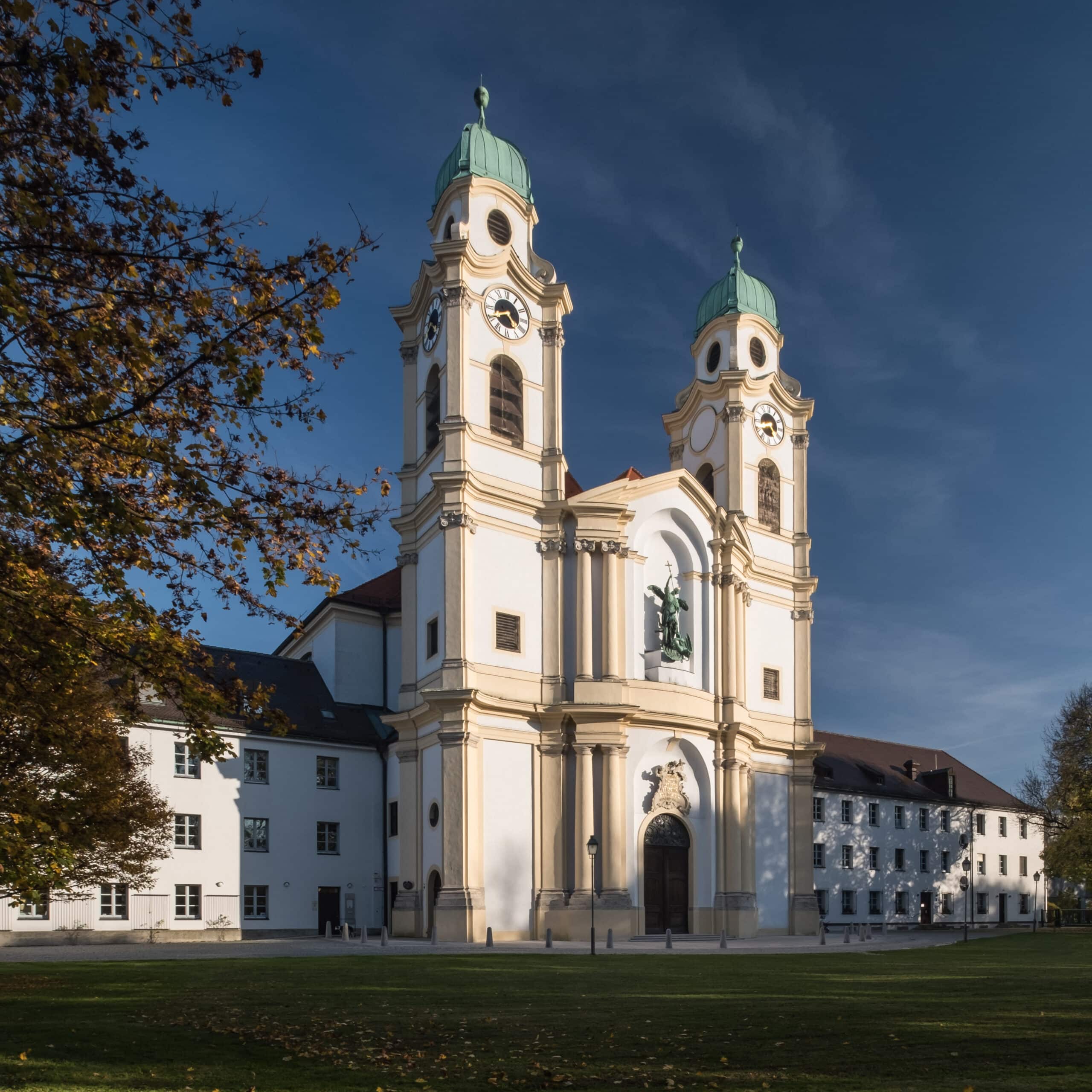
The decision to study St Michael was made for me by events but it was a serendipitous, if daunting one. As already noted, the church is one of the masterpieces of the German rococo and is a key work of Johann Michael Fischer (1692-1766), who was amongst the finest and most inventive of the movement’s architects. Equally brilliant in their fields were the stuccoist and fresco-painter Johann Baptist Zimmerman and the designer of the high altar, Johann Baptist Straub. This star team worked for the Archbishop of Cologne, Clemens August, whose predecessor had founded a brotherhood of St Michael at Berg am Laim. These archbishops were both brothers of their contemporary Electors of Bavaria and the church of St Michael therefore stands partly as a monument to fraternal competition, sited on the outskirts of the then electoral capital and within distant view of the Elector’s Schleissheim and Nymphenburg residences. Work began in 1737, the church was consecrated in 1751 and Straub’s high altar was installed in 1769.
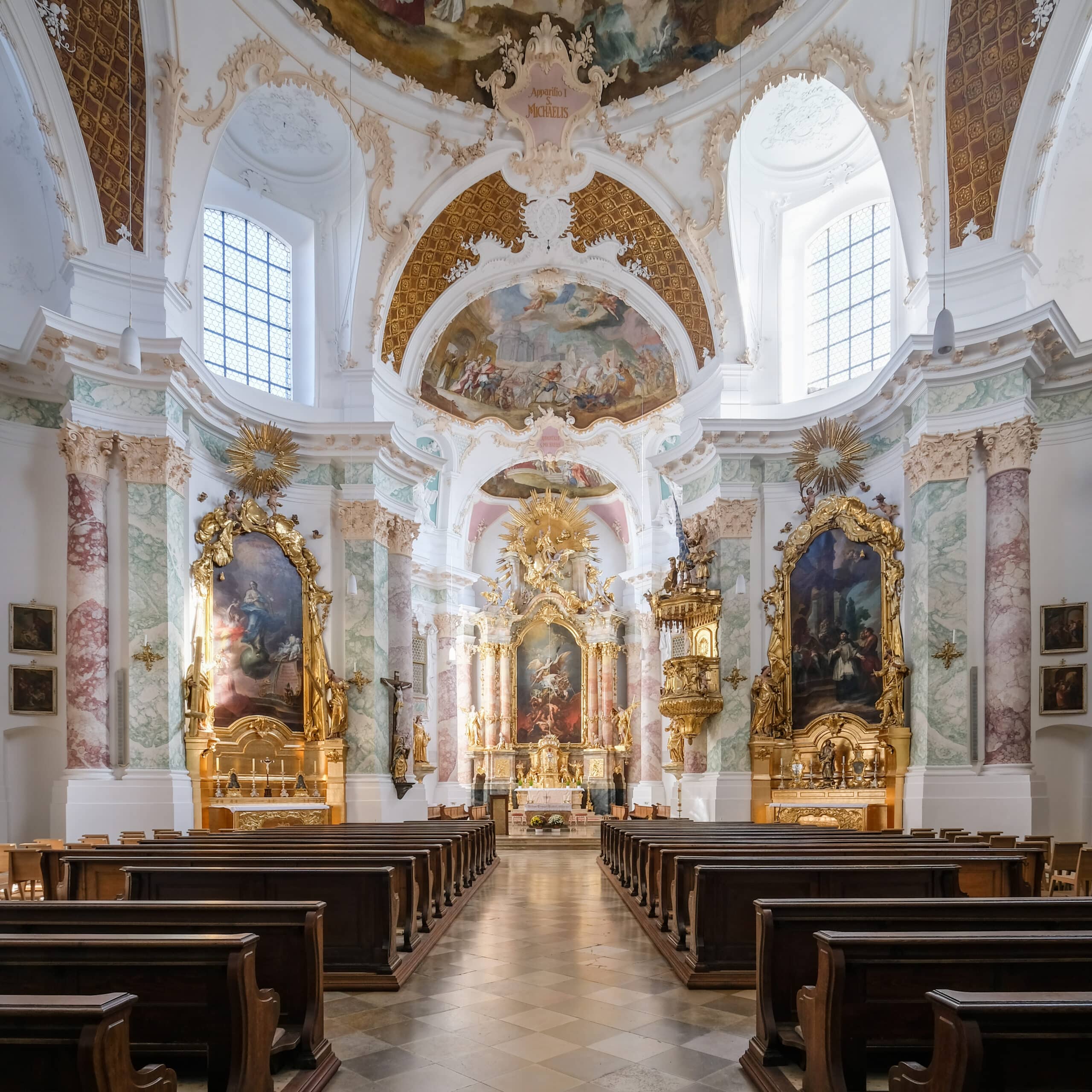
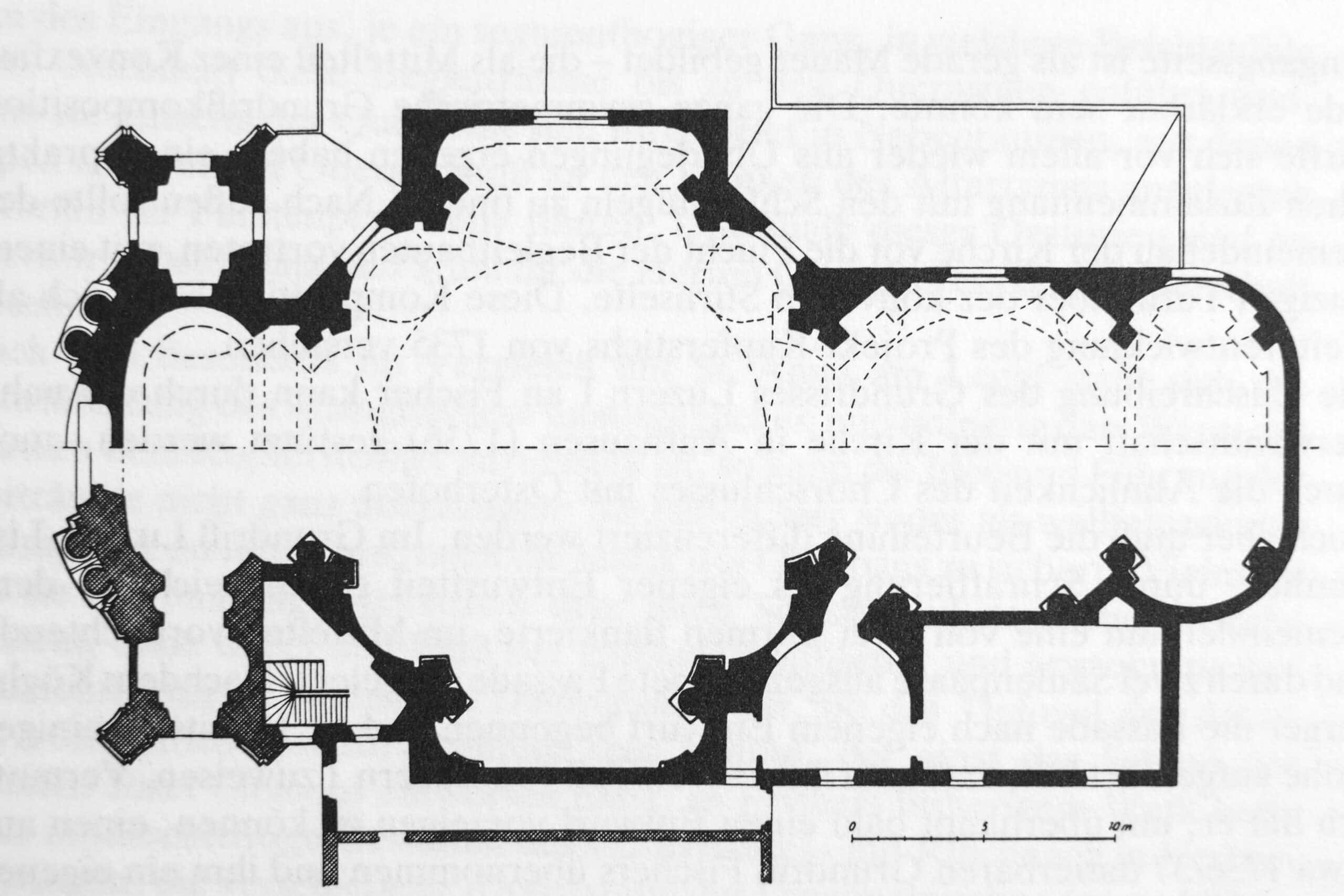
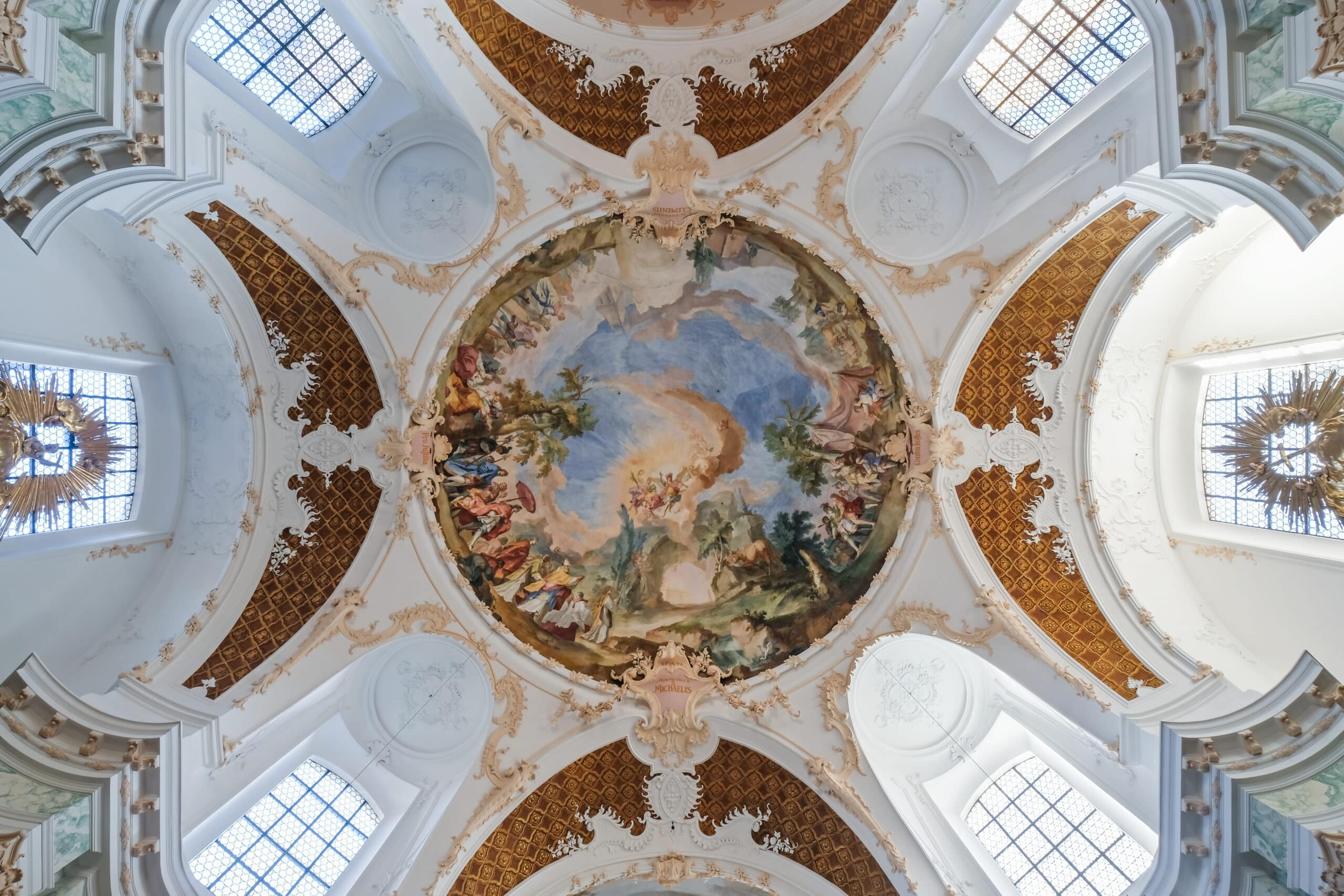
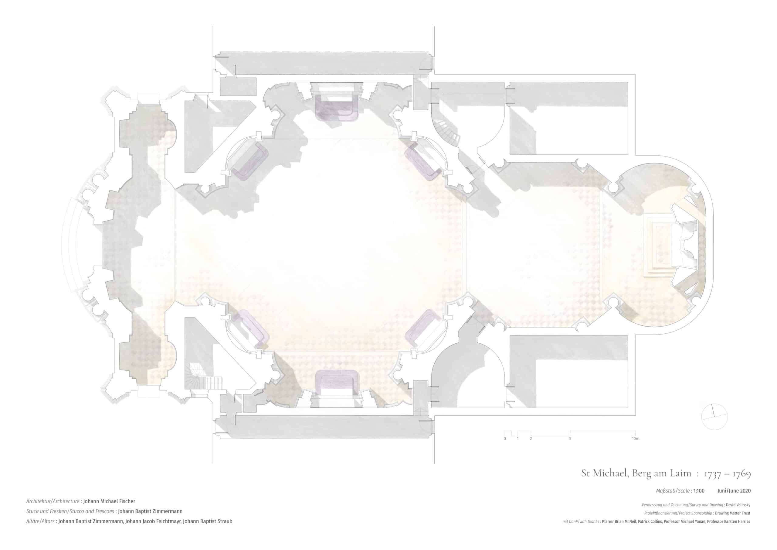
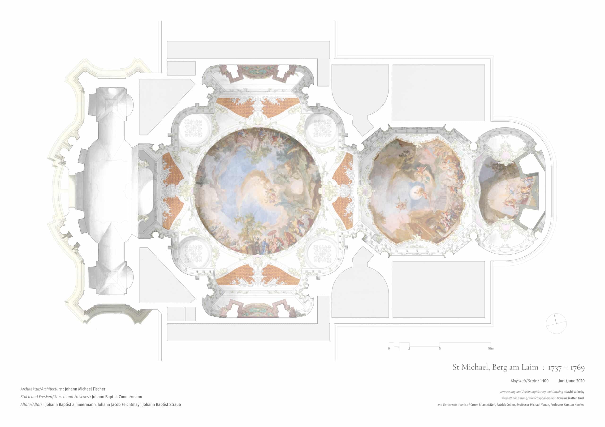
The complexity of the building in both plan and three-dimensional modelling is particularly daunting to the amateur surveyor. The church interior consists of four unique spaces, of which the largest, the centralised ‘nave’, is Fischer’s most enigmatic creation. His architecture often plays with variations on centralised octagonal spaces (of which the adjacent ‘choir’ for the Brotherhood is another example) but as can be seen from the drawings, the plan of this space is indescribable. The vault above it is so completely cut away both on the cardinal points and the diagonals that it is barely there are all. Only in the thankfully pure circular ring at the base of the shallow dome above is resolution achieved.
This architectural complexity, combined with the intentional use of stucco to hide or disguise architectural junctions and forms leads us to a prosaic observation – defining the forms and dimensions of this architecture is remarkably difficult. The equipment that I used ranged from tools that Gruber would have used in 1952 such as tapes and a folding rule, to a laser distance measurer and level, equipment that allow measurements to be taken without requiring the surveyor to physically access both ends of the line that he or she is measuring. Such equipment makes the taking of measurements considerably more straightforward, but ultimately the process and the end goal is the same: one measures the distances between pairs of points over and over again in order to create two-dimensional orthographic representations that must be constructed on a flat plane from these measurements.
Methods and approaches
Before the trip I spent an afternoon in the chapel of Pembroke College in Cambridge with Patrick Collins, an experienced surveyor, who was able to impart some invaluable tips and tricks of his art as we considered how to survey the relatively simple rectangular space as an exercise. He asked what the reader may be thinking: why was I not using a laser scanner to create a three-dimensional model, from which orthographic projections could subsequently be taken? The cost was prohibitive of course, but I also felt that such an approach could risk providing an overload of information, given that I simply wanted to create two-dimensional 1:100 drawings. I mention the scale because it is easy to forget that digital information does not have any. Anyone familiar with CAD drawing will have wasted time carefully delineating details and worrying about measurements that cannot be read or seen when the drawing is subsequently made into an object by printing. At the time I felt that the rough granularity of two-dimensional linear surveying would suit me better, or at least just as well, as the basis of a set of physical drawings.
The process of surveying and drawing that I have since undertaken leads me to a more complex set of conclusions. It would be impossible then or now to deny that a three-dimensional survey would have been faster, more accurate, and far more comprehensive than the laborious process of measuring straight lines in a space that has very few of them. Hindsight highlights the perhaps obvious facts that it would also have allowed the interrogation of a model separate from the building itself that could be infinitely examined beyond the period on site, and defined parts of the complex building that linear measurement could not – as I describe below, many elements of the building’s form proved impossible to determine with the tools at hand. However, ‘interrogation’ is the key here. A three-dimensional model created by a scan is a record of an object that requires a small degree of planning from the operator on site in order that information is efficiently captured. The model stands in for the building and must itself be interpreted (e.g. through slicing) in order that a drawing might be created. It can be interrogated, but this is a choice, not often a requirement. By contrast, a two-dimensional survey is itself an active interrogation of the building, even if ultimately an answer cannot be found to some questions. The process of recording and checking numbers reveals aspects of the building to the surveyor that would otherwise escape notice because they do not register visually. This fundamental difference is analogous to that between photography (at least quickly-snapped photography) and sketching. The record photograph, while not denying the possibility of active engagement by the person pressing the shutter, does not demand it. The process is quick and the result can be interrogated later, or not. A sketch is not the same thing. Its purpose is not the end result, but the process of production, through which the sketcher learns about the subject through observation and interrogation. It is ‘drawing to find out’, to re-direct Michael Merrill’s succinct description of Louis Kahn’s design-sketching process. The measured survey allows the surveyor to find out, in addition to recording the building. However, like the sketch, the information discovered through process inevitably remains for the most part with the person that created it: somebody looking at the sketch or survey does not learn all that its creator has. The information must therefore be imparted by other means, appropriate to its nature. The scale, proportions and quality of the architectural space are best imparted by drawings, such as those that formed the second process of this study. Other facts are most clearly imparted by words, hence the desire and need to write about the survey. We will look, therefore, at the survey and the ‘drawings’ it produced for what they tell us about the building, before looking at the experiment in representation that was based on them.
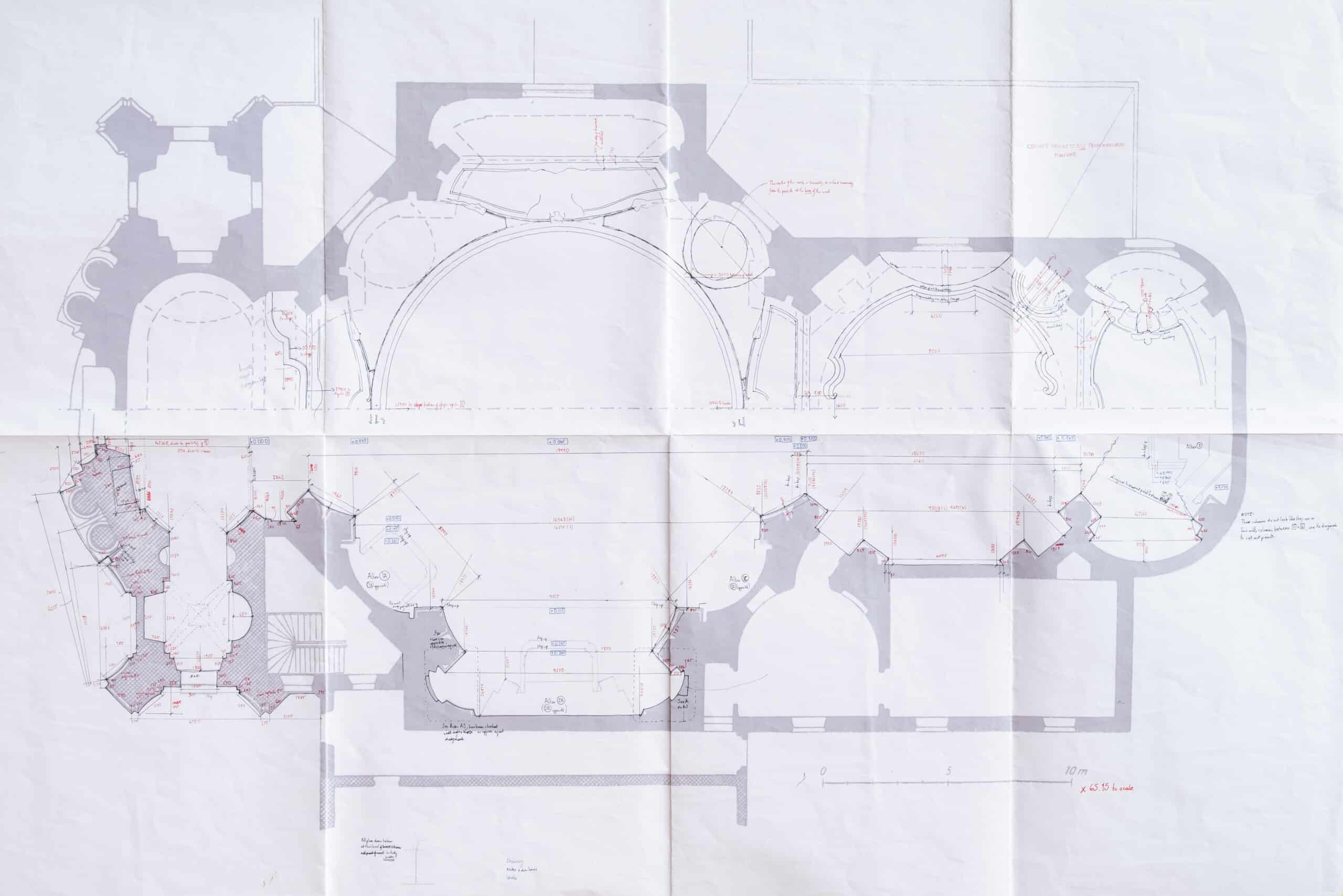
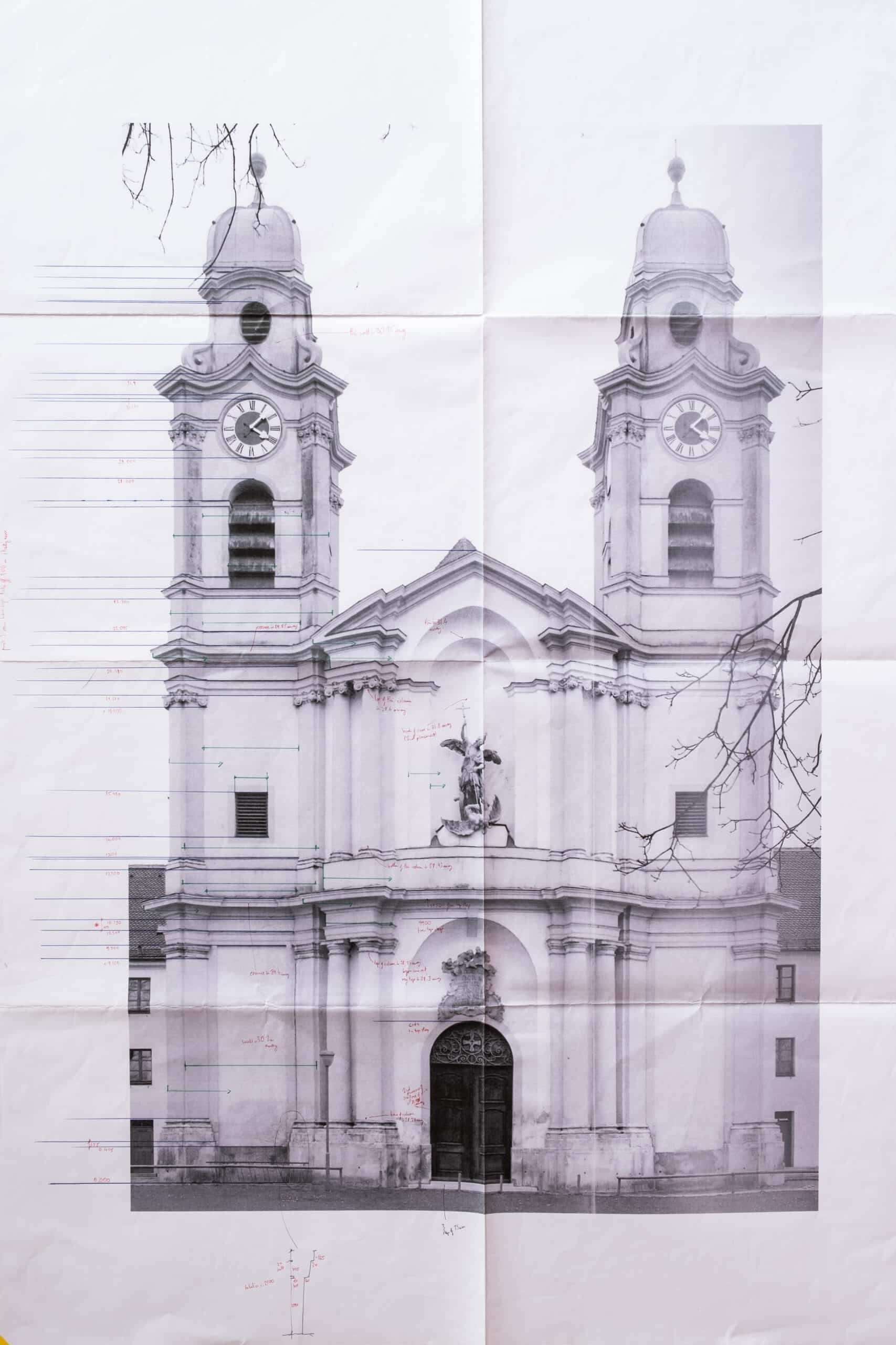
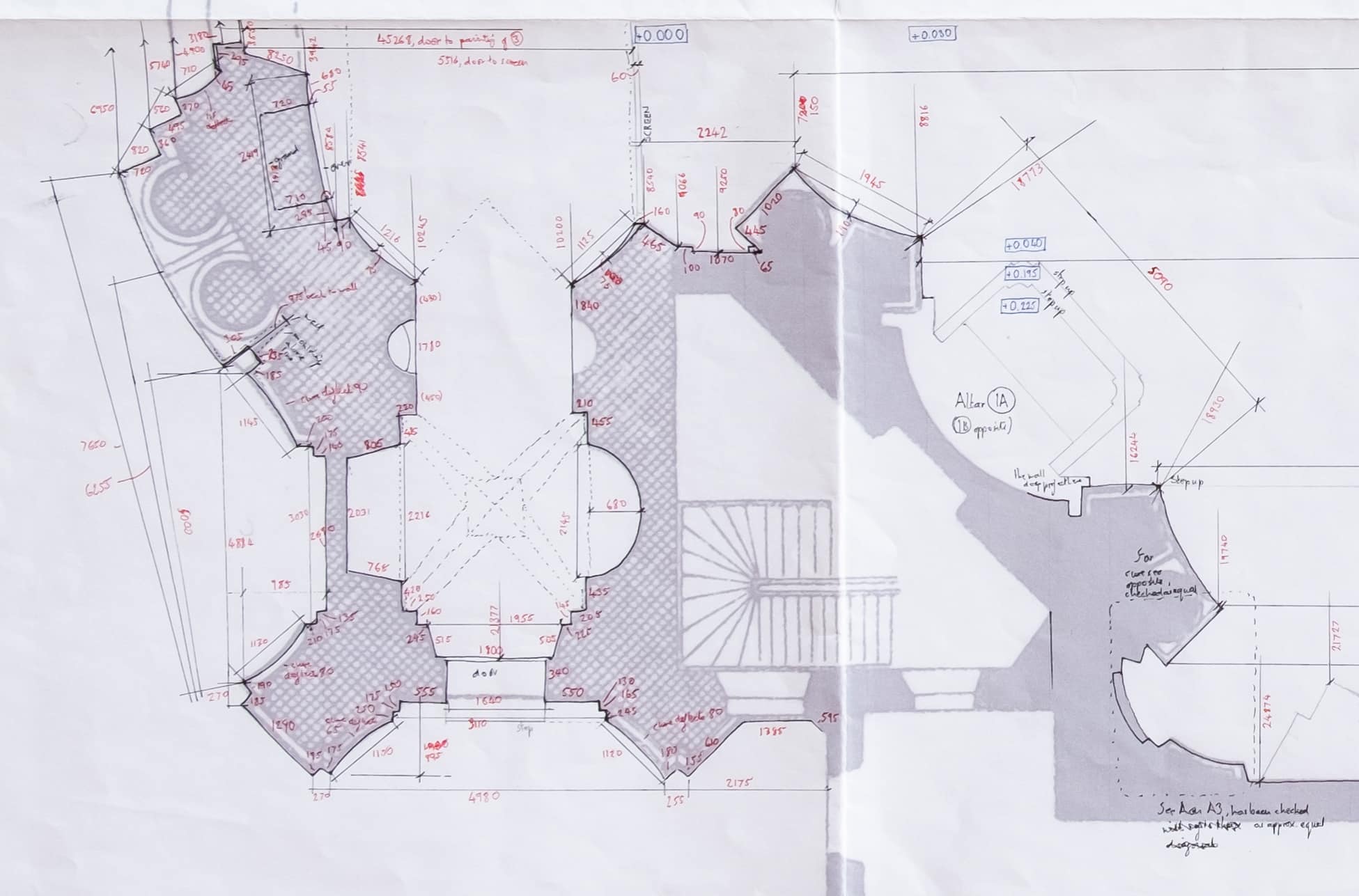
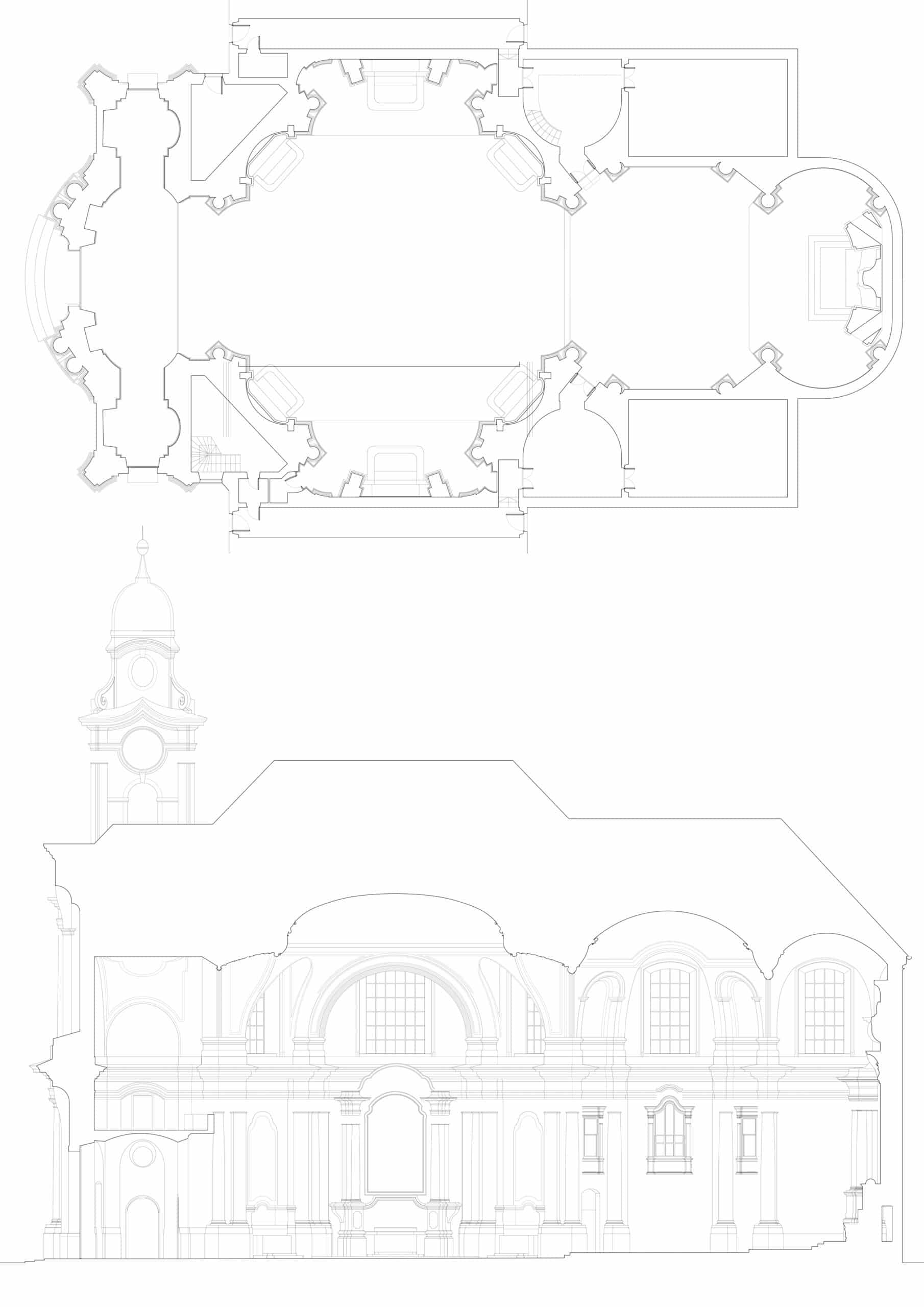
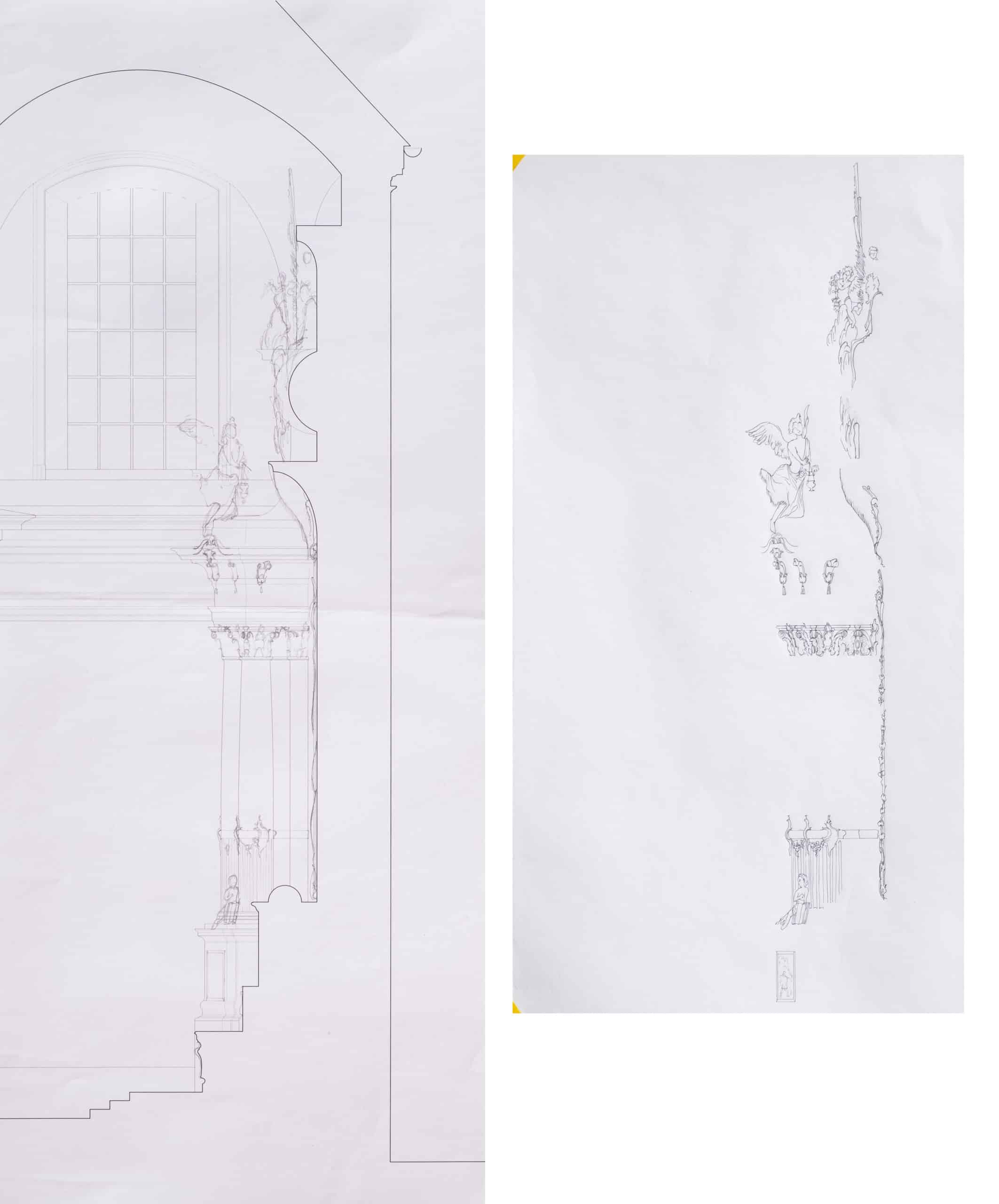
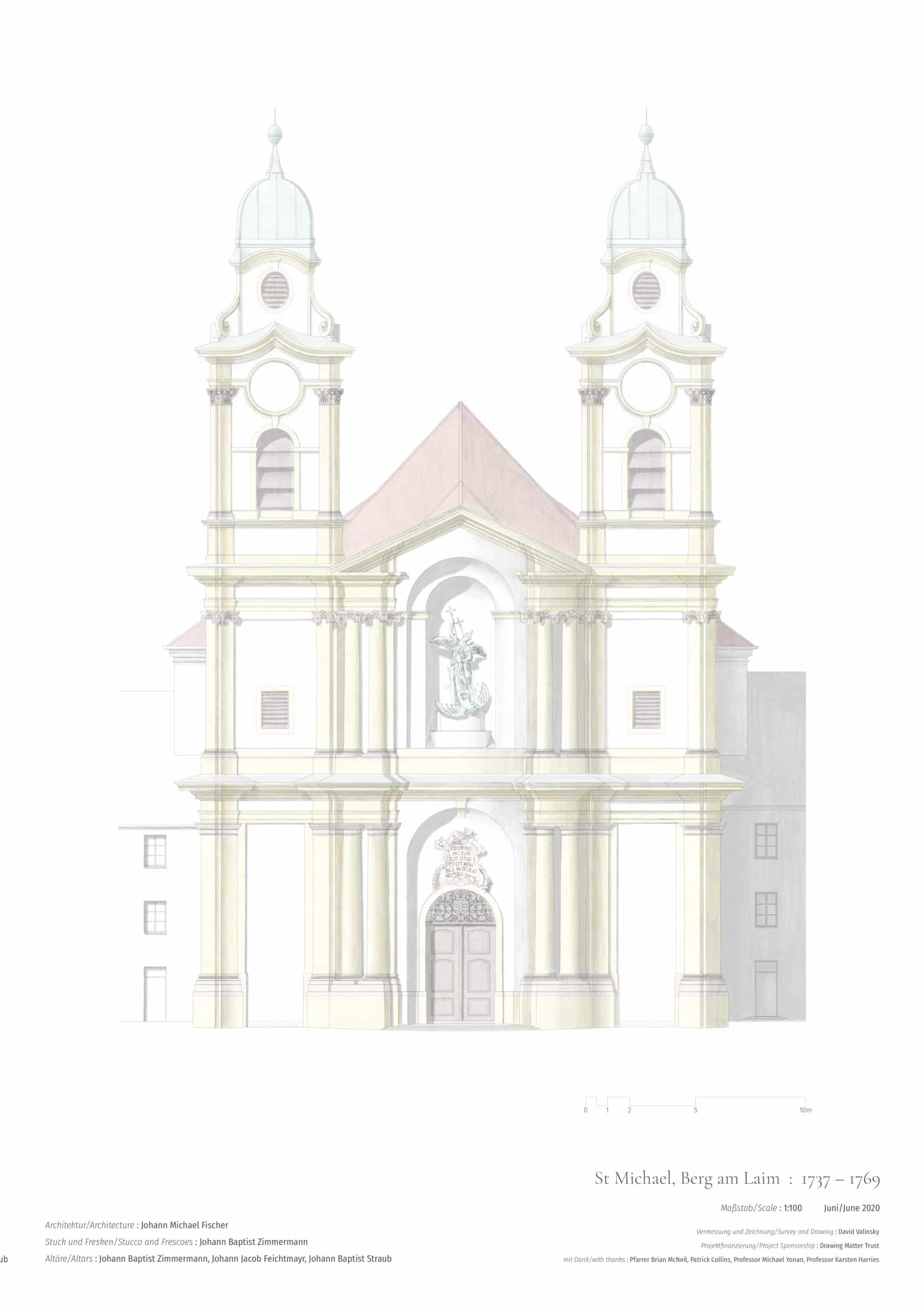
The 1952 plan and section provided a useful template onto which measurements could be notated and they served as a starting point for planning the survey. No elevation drawing of St Michael existed, and so a photograph was used in its stead. One taken from a distance was selected to reduce the inherent problem of perspective, though it was necessary to remain conscious of this limitation both during the survey, and while creating a drawing from it.
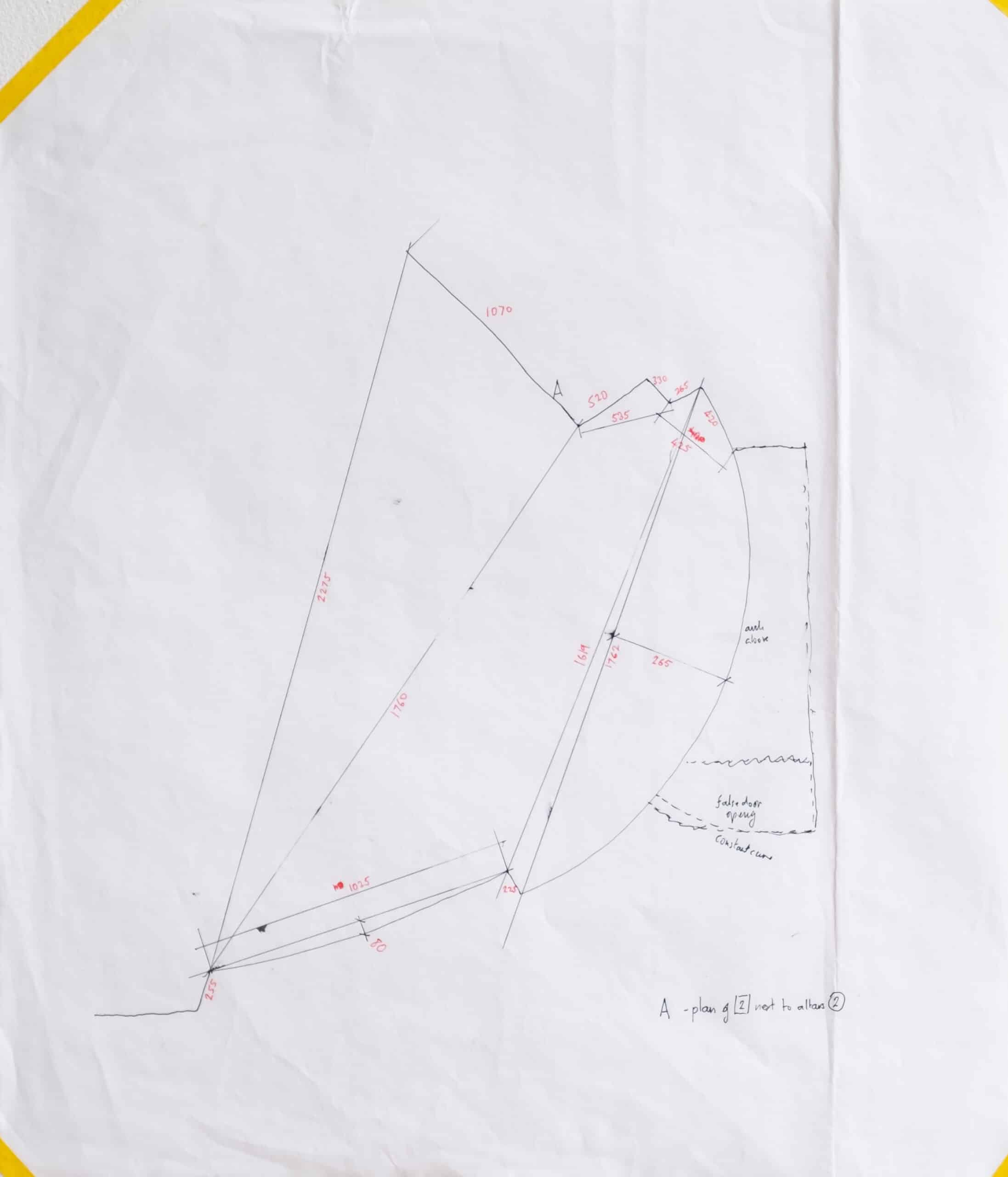
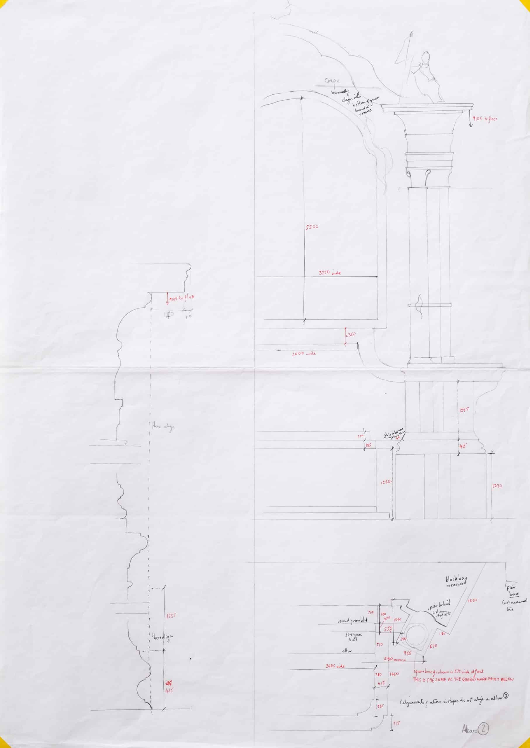
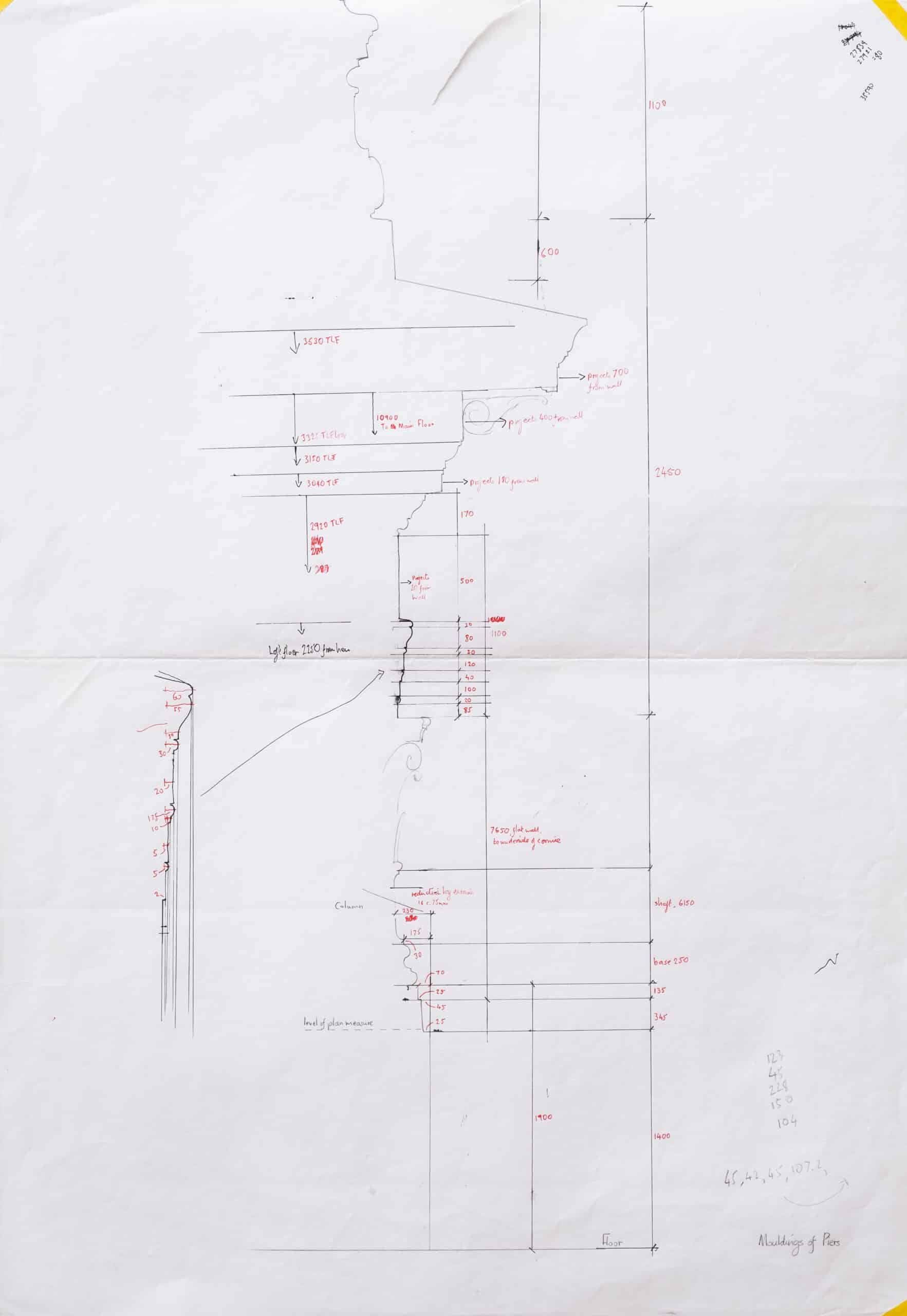
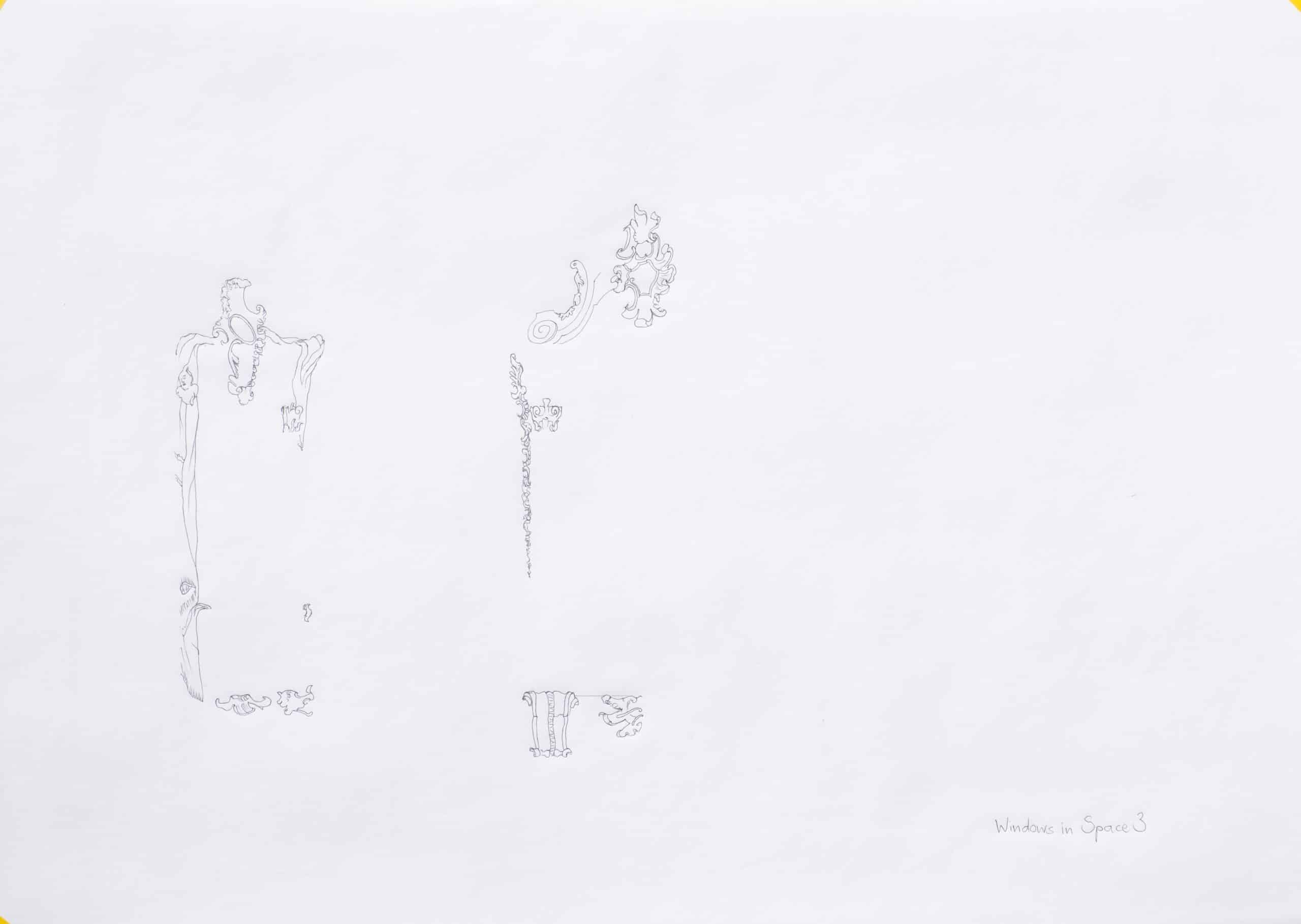
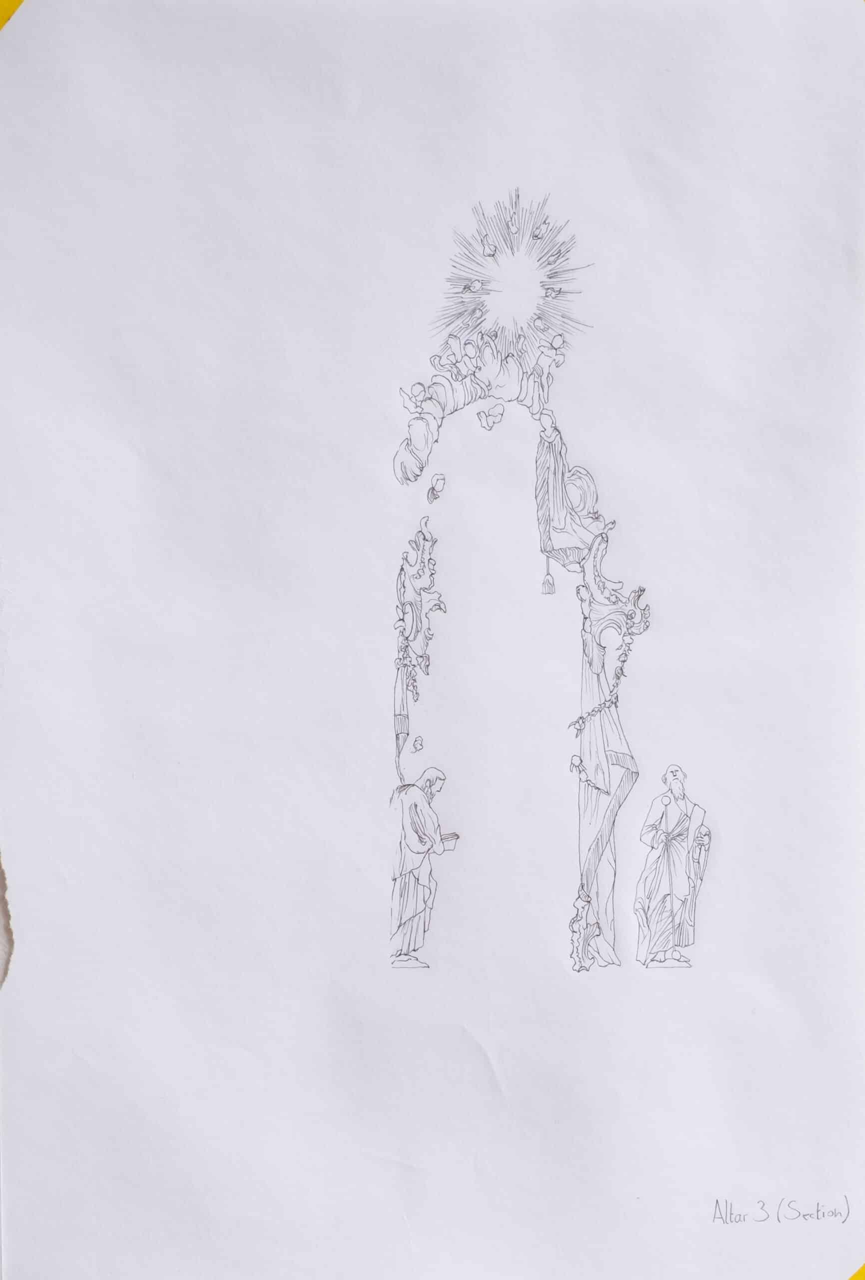
All three base images were magnified to fill an A1 sheet so as to provide plenty of space for clearly noting dimensions and levels. Despite this, the complexity of the plan required some details of its outline to be sketched separately at a bigger scale to allow sufficient dimensions to be taken. Similarly, the fragments of the vast altars that could be measured were set out on separate sheets.
I began the survey by defining some fundamentals and undertaking dimensional checks. I determined that I would measure to the accuracy of 5mm and that it was to be assumed that the building was ‘square’ and symmetrical, unless the survey demonstrated significant deviations – I would not attempt to draw minor discrepancies arising from building and finishing tolerances. Perpendicular and diagonal dimensional checks between key points on the plan bore this out with only a couple of centimetres deviation at most between the north and south sides of the plan. It was also important at the outset to determine where the plan would be cut. The interior columnar architecture of St Michael is raised so that the column bases are at head height on a simple base that runs around the whole building. A step in this base at a convenient height was selected as the plan cut for the survey and checked for consistency around the building with a laser level.
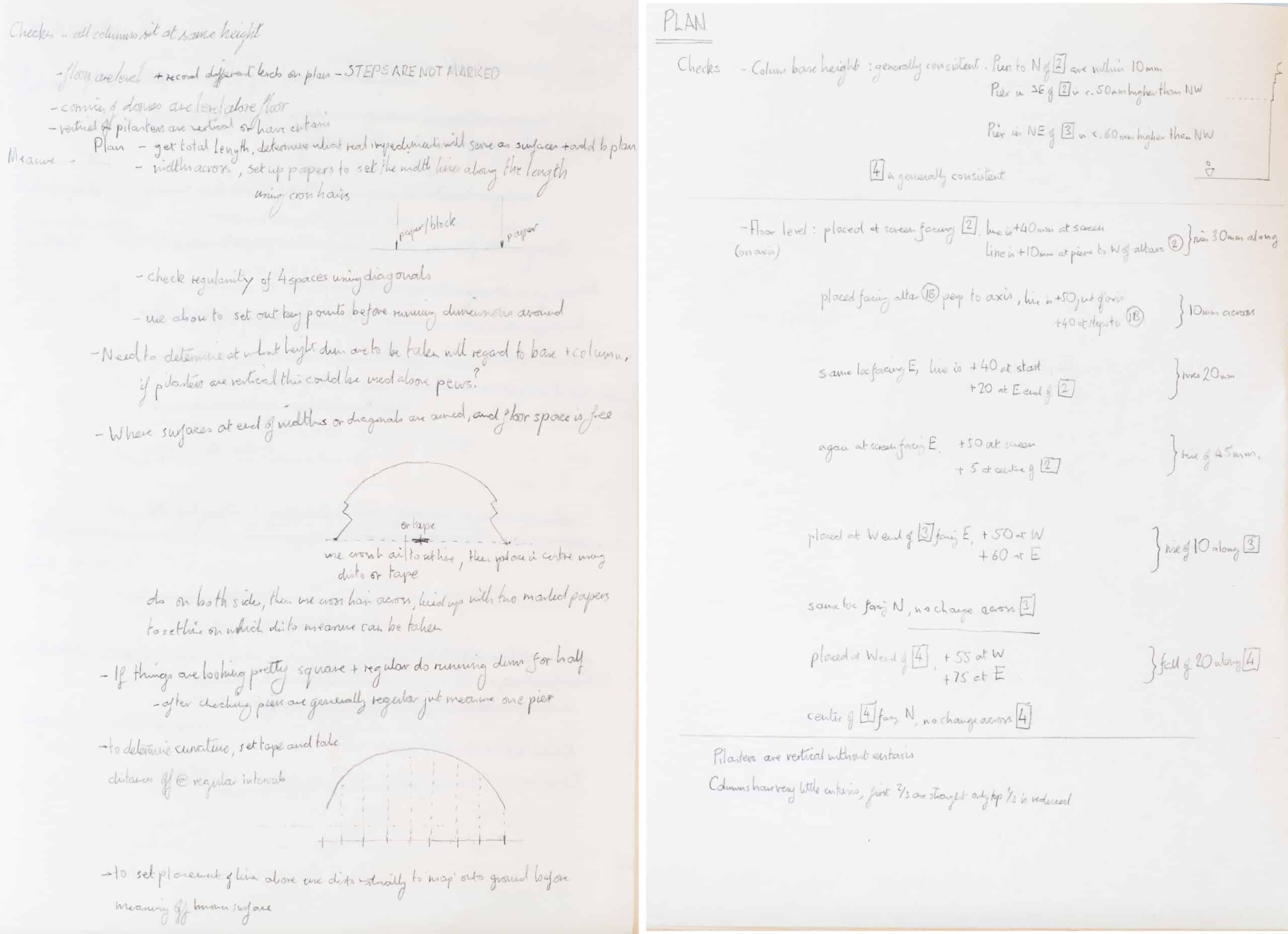
Once the framework for the survey was secure I began the process of measuring the plan, the complexity of the outline requiring much of it to be triangulated. Curves were determined by setting a straight line between the start and end points with either a laser or tape and measuring the perpendicular distance between this chord and the arc at various points along it.
Unexpected findings
This process brought various aspects of the 1952 plan into question of which two examples will suffice. Either side of the oval narthex at the front of the church sit vaulted square spaces at the base of the façade towers. As one would expect architecturally and structurally, these are located centrally below the towers and not, as the 1952 survey drawings show, biased towards the centreline of the building. This appears to be a straightforward surveying error that has nevertheless been reproduced ever since, a warning against accepting drawings without interrogation.
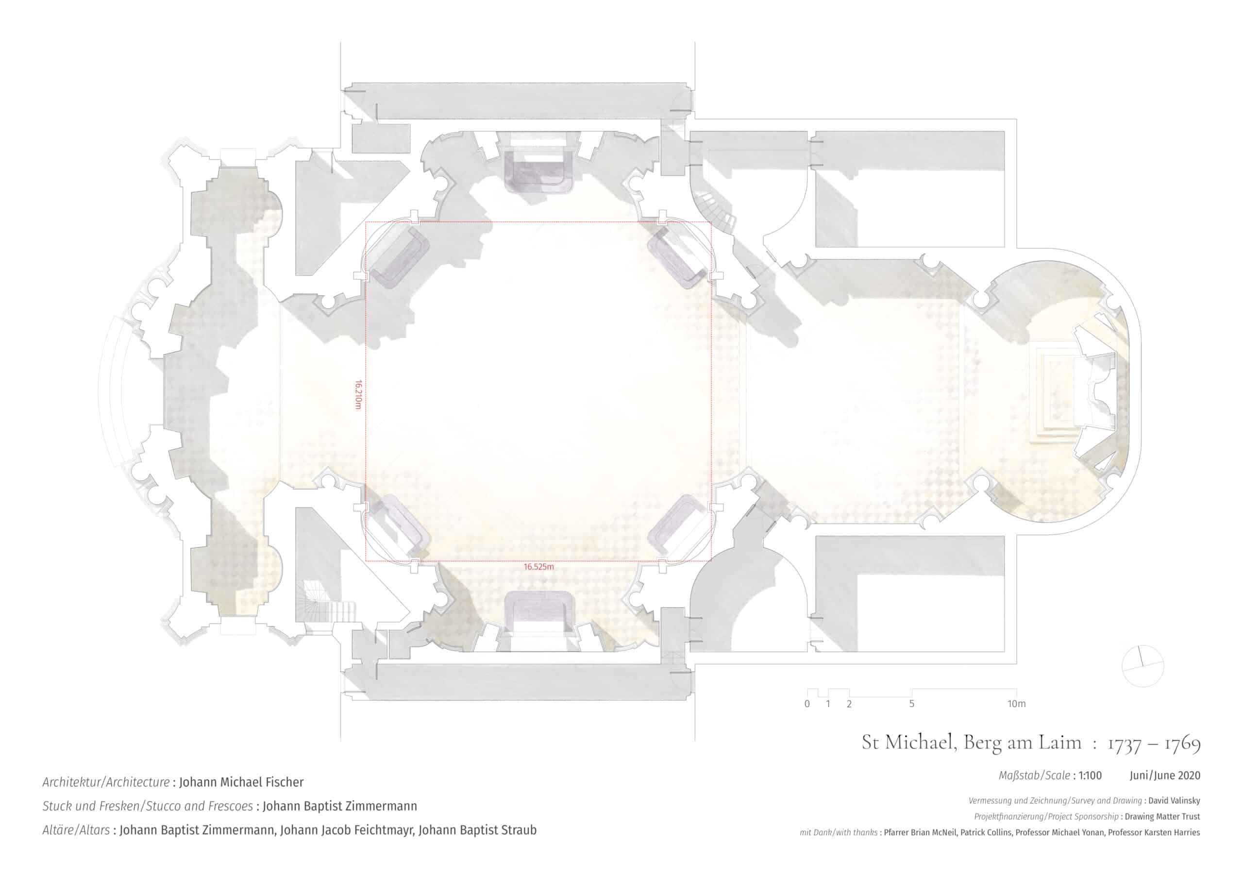
The second example demonstrates well the value of taking linear dimensions as a surveying technique. As complex as the final plan of the centralised ‘nave’ is, it is fundamentally set out around a square of just over sixteen metres. However, the survey demonstrated that this ‘square’ is actually 300mm longer than it is wide, something that was only noticeable because I was dealing directly with each measurement. This is a curious irregularity. It is too big to be put down to contemporary construction accuracy (which as already noted was found to be much better than this), but not big enough to be experienced, particularly in such an overwhelmingly complex space. Though I can only speculate, an explanation could lie in the complicated early planning and construction history of the building, various theories of which exist due to the tantalisingly fragmentary documentary evidence. What is known is that Fischer was replaced at the earliest stages of excavation work in late 1737 by Philipp Jakob Köglsperger, who had recently arrived at the Munich court. Köglsperger directed site work until early 1739 when his clear limitations became untenable and Fischer was hurriedly brought back. During the long legal dispute that followed, Köglsperger claimed that he had both raised the façade towers two metres out of the ground and laid the foundations for the whole building. He also admitted to some errors arising from Fischer’s ‘passions’. If Köglsperger’s claims are true (his difficult legal situation and desire for payment would have encouraged him to overstate his contribution), it could be that by the time Fischer was reinstated and the setting-out problem detected, remedying the situation was either not possible without significant demolition at one end of the building or the other, or not considered worthwhile by Fischer. It is worth noting that the muscular interior architecture is constructed entirely from plaster and timber, so it could have been arranged relatively freely within the masonry shell. This freedom would have allowed the apparently symmetrical vault to incorporate the minor distortions necessary to create the regular circle at the base of the dome. Importantly for this discussion about the value of surveying, if this discrepancy in the nave was detected in the 1952 survey, the information was either not passed on by the surveyor, or was deemed unimportant because it was not part of the design intent.
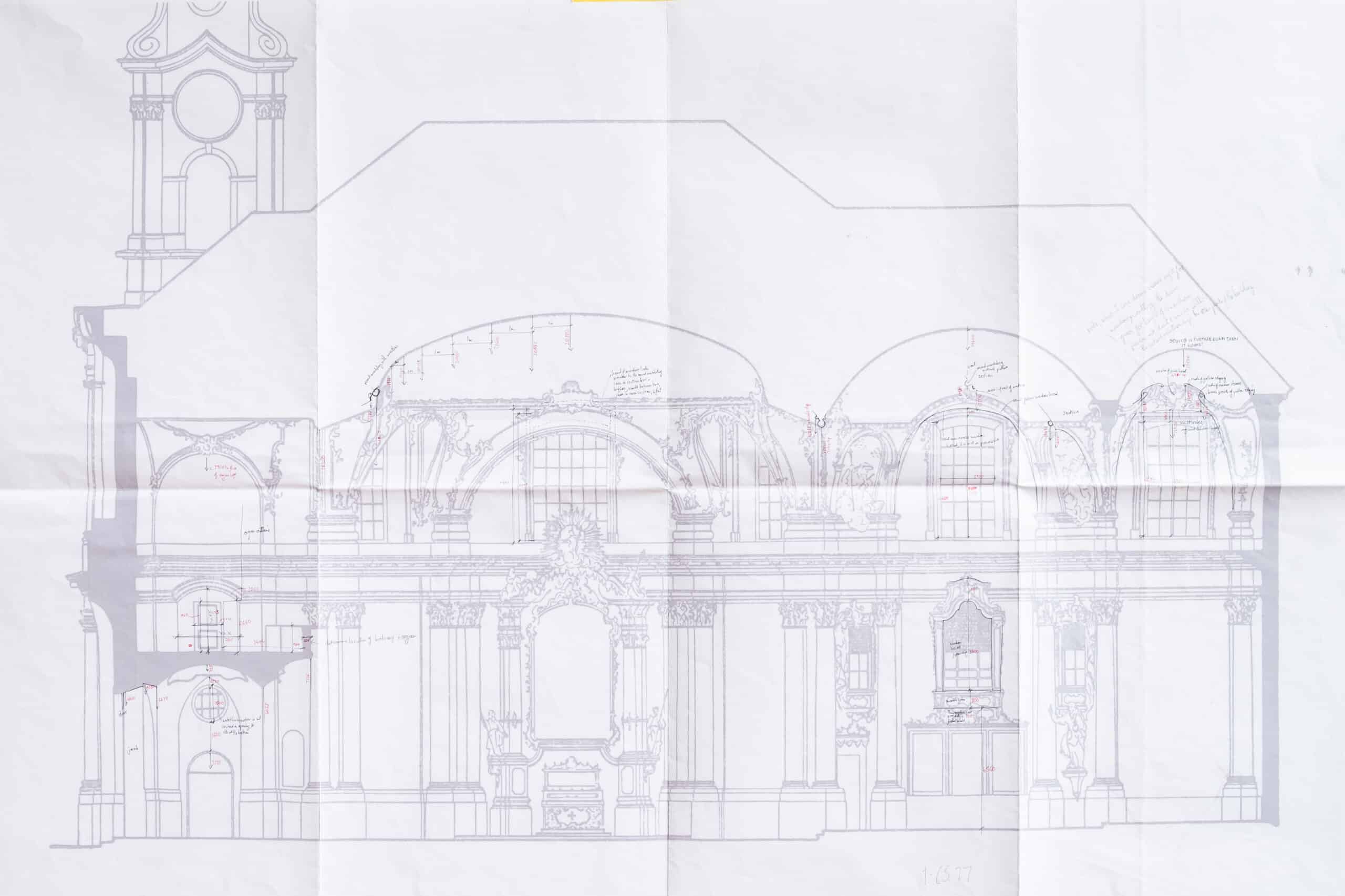
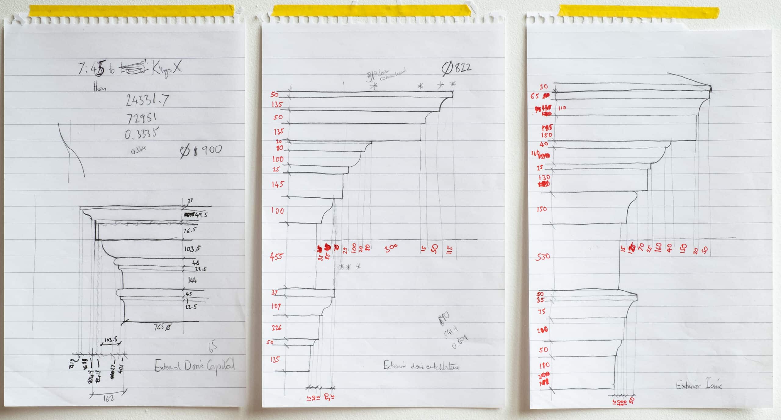
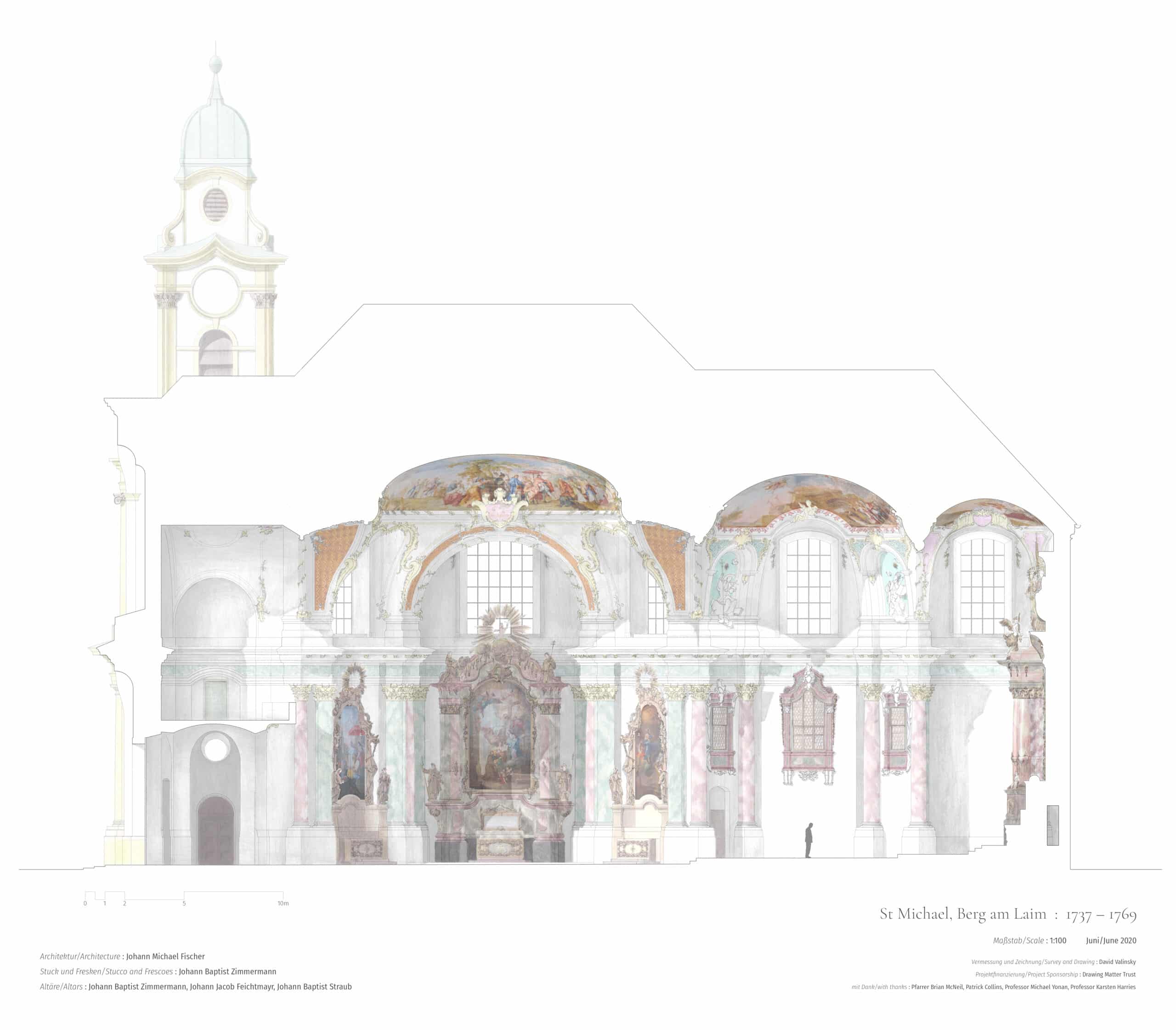
The process of surveying the section and the reflected plan of the vaulting was far more troublesome than the plan for three reasons: the lack of access; the abundant stucco and sculpture masking clear ‘points’ to measure to; and the need to survey what lies behind the cut line, in addition to the cut line itself. The resulting measured survey information was consequently far more fragmentary and would undoubtedly have benefitted greatly from three-dimensional scanning. Measurements that were taken were limited to the cut line and those elements of the elevation beyond that could be defined, windows and doors for example, or easily accessed, such as the organ loft. The organ loft made possible the direct measurement of the architrave above the columns that runs around the whole building, the only moulding other than the column bases that could be measured on site. Other mouldings on the section and elevation relied on extrapolation and scaling from photographs, carefully worked through on A5 sheets during the process of drawing.
However, despite the limitations, the survey of the building section did enable issues with the 1952 drawings to be identified. The vault above the high altar serves as a worthwhile example because of its complexity. My measurements demonstrated that the surface of the vault was much flatter than the parabolic curve shown in the 1952 drawings, contrary to the evidence of the eye – a note on my survey sheet reads ‘this is much lower than it looks.’ There are many such moments where the shapes of surfaces and edges are not as the eye perceives them and where the subsequent process of drawing was one of slowly and iteratively forming a best guess between the measurements that I could gather and photographs. It is worth saying, however, that this ‘confusion’ is fundamental to one’s experience of this building and the wider German rococo; parameters that are literally indefinable by the mind’s eye enhance the irrationality and theoretical infinity of its spaces.
As a final example of lessons learnt from the survey process, another observation is worth making about this altar room, if a hesitant one. Hesitant because the presence of the altar itself made the setting out of the architectural framework here particularly difficult. A glance at the plan suggests that the pair of columns that frame the altar mirror the pair that divide the altar room from the choir. However, my survey suggests that they are actually 250mm closer together. No direct measurement is possible between them, the positioning being determined instead by triangulation from other points. This ‘pinching’ of the columns is, however, echoed by the definite asymmetry from front to back of the fresco above and the surrounding stucco, as well as the surface of the vault itself.
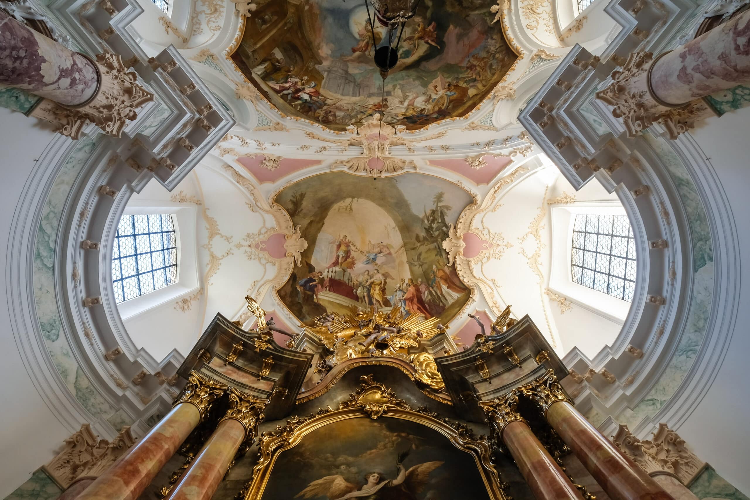
All appear to be drawn towards the altar as if acted upon by a gravitational pull. However, if this is a conscious attempt to frame the altar for the viewer standing at the other end of the church it is a subtle one as the three other pairs of columns that frame the view from the entrance are set out equally – this is not part of a bigger perspectival play. A more mundane answer for this pinching may be visible in the photograph where it is quite obvious that the flat clerestory windows are not parallel but are turned inwards towards the altar as the external wall curves around it. In section the roof timbers land on the wall behind the altar, very close to the plaster vault. While the interior architectural design may have aimed at symmetry, the constraints of the exterior architecture and structure on the space are not symmetrical from front to back and may have forced distortions upon the interior, or indeed encouraged them as a means of disguising the irregularity.
From survey to drawing
Armed with a plethora of survey measurements and hundreds of photographs I returned to the UK with the knowledge that my original intention of creating a drawing entirely by hand would be, if not theoretically, then at least practically impossible. It was clear that a good deal of triangulation, extrapolation and trial and error would be involved and this approach pointed strongly towards digital drawing, at least to create a basic framework that could be edited and manipulated to find a best fit with the fragmentary information that I was able to collect. However, it was also clear that digital drawing would not be useful medium in which to attempt drawing freely-flowing stucco or expressive sculpture and I had no desire to strip the building back to the architectural skeleton by simply skirting around its rich ornamentation, to do so would be to fail at the first step in my intention to present something of the experience of this architecture. I resolved, therefore, on a collage approach that for the most part was taken through to the conclusion of the drawing process. Digital drawing would be used as much as possible for the linear aspects, supported by hand-drawn fragments where necessary to describe sculpture, stucco and other ornamentation. Digital collaging would allow photographs of frescos and altar paintings to be incorporated, together with the colouring that is so important in making this rich architecture legible.
The differing degree of measured information that I was able to gather for the four drawings (plan, section, elevation and reflected vault plan) quickly made itself felt during the initial drawing process: the plan could be accurately set out and served as a basis for constructing the other projections, but increasing amounts of extrapolation and educated guess-work based on the photographic record were required as the drawings rose above the plan. Some parts of the section and vault plan were redrawn countless times as they fed off each other and additional information was incorporated. With this laborious iterative process complete, the digital drawings were printed and used as a basis for the fragments of hand drawing.
In order to incorporate an appropriate amount of detail in these hand-drawn fragments, they were drawn at 1:50 and digitally reduced to form part of the 1:100 drawings. Digital mirroring and reproduction of the line drawings and the hand-drawn elements was used a great deal where symmetry or repetition in the original building allowed.
Experimenting with colour
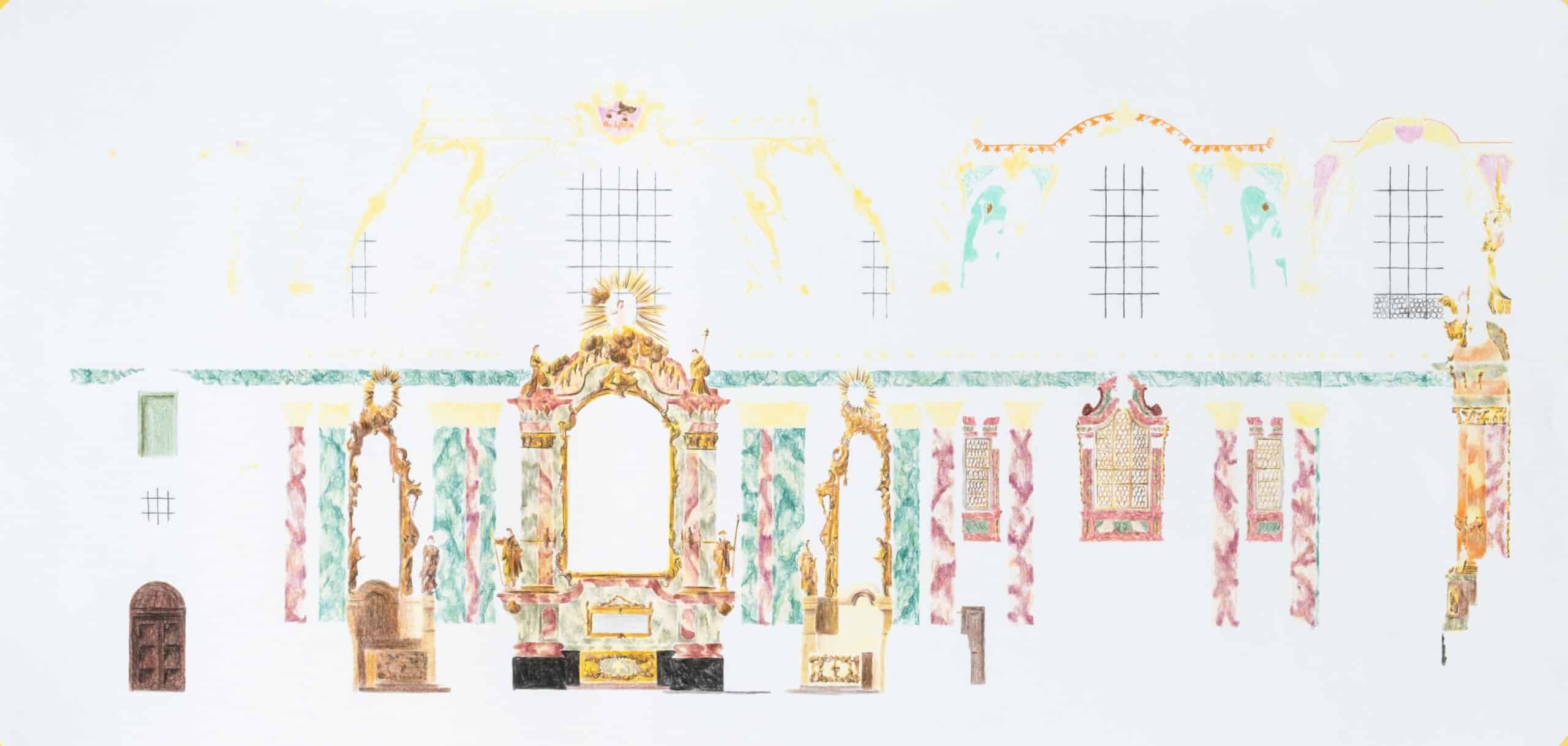
An attempt at collaging digital and hand-drawn elements with colour was first made on the elevation. The challenge was to combine the digital and hand-drawn elements so that they did not jar. The inherent life in hand-drawing was compromised in order that the drawing could read as one. Digital lines were lightened slightly while the hand-drawn elements were drawn heavily and darkened so that they read consistently with the framework. In this first attempt, colour was added digitally with a textured base (a scan of a pencil rubbing on heavy cartridge paper), the intention remained to create a drawing and not a digital rendering, colour supporting the image but not dominating it.
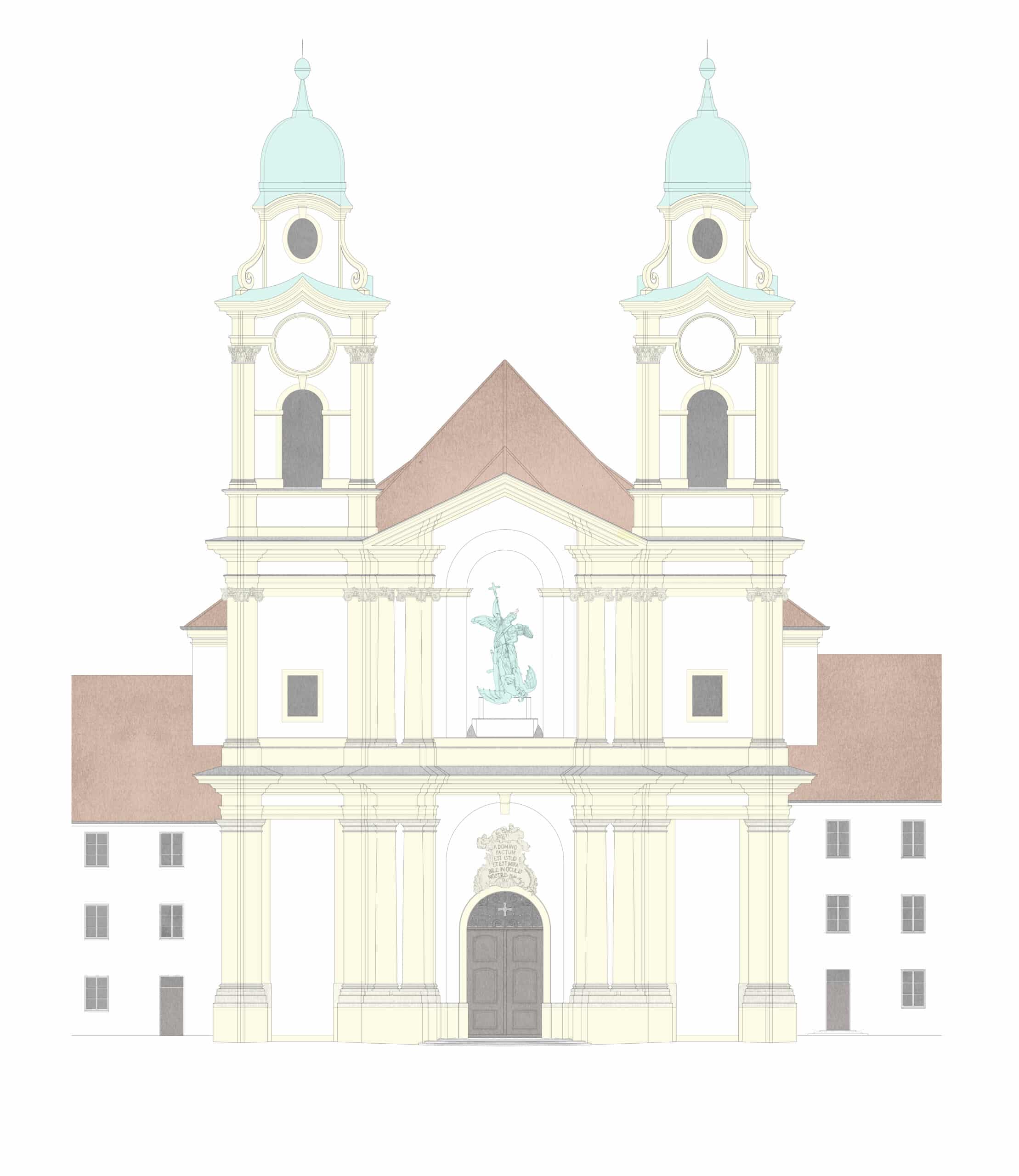
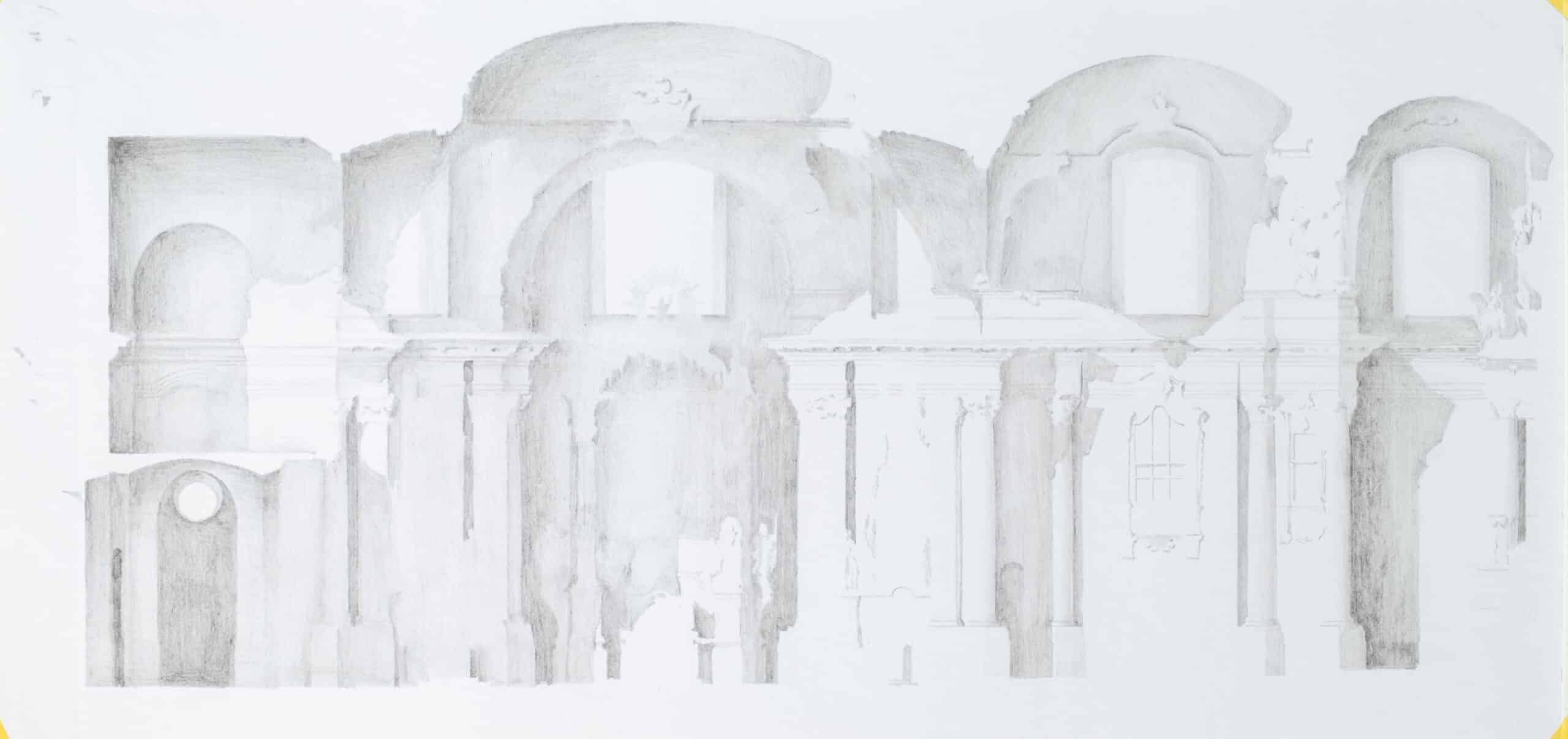
The process of constructing this draft and the result were felt to be unsatisfactory for three reasons. The digital colouring was undertaken using Adobe Photoshop by selecting areas within the digital lines and applying colour to them; this process did not work easily with the hand-drawn fragments and the result was too uniform. In addition, it became evident that shadow would need to be added as an additional element to the collaging process to help the viewer read the drawing. In the case of the elevation, the powerful projection of the central section was illegible and it was clear that the section and vault plan would benefit significantly from shading to indicate the modelling of the surfaces, and help depth to be read by the viewer.
Drawing by hand
These findings having been determined through putting together the relatively simple elevation, it remained necessary to piece together the hand-drawn fragments for the section and vault plan. While the small number of fragments for the elevation, over-door and niche sculptures and the ionic and Corinthian capitals, could be fairly easily created through tracings of scaled photographs (again taken from a distance to minimise perspectival distortion) and the basic proportional principals of the orders, the stucco and sculpture of the interior, located high above the viewer’s head, was less-straightforwardly drawn in orthographic projection.
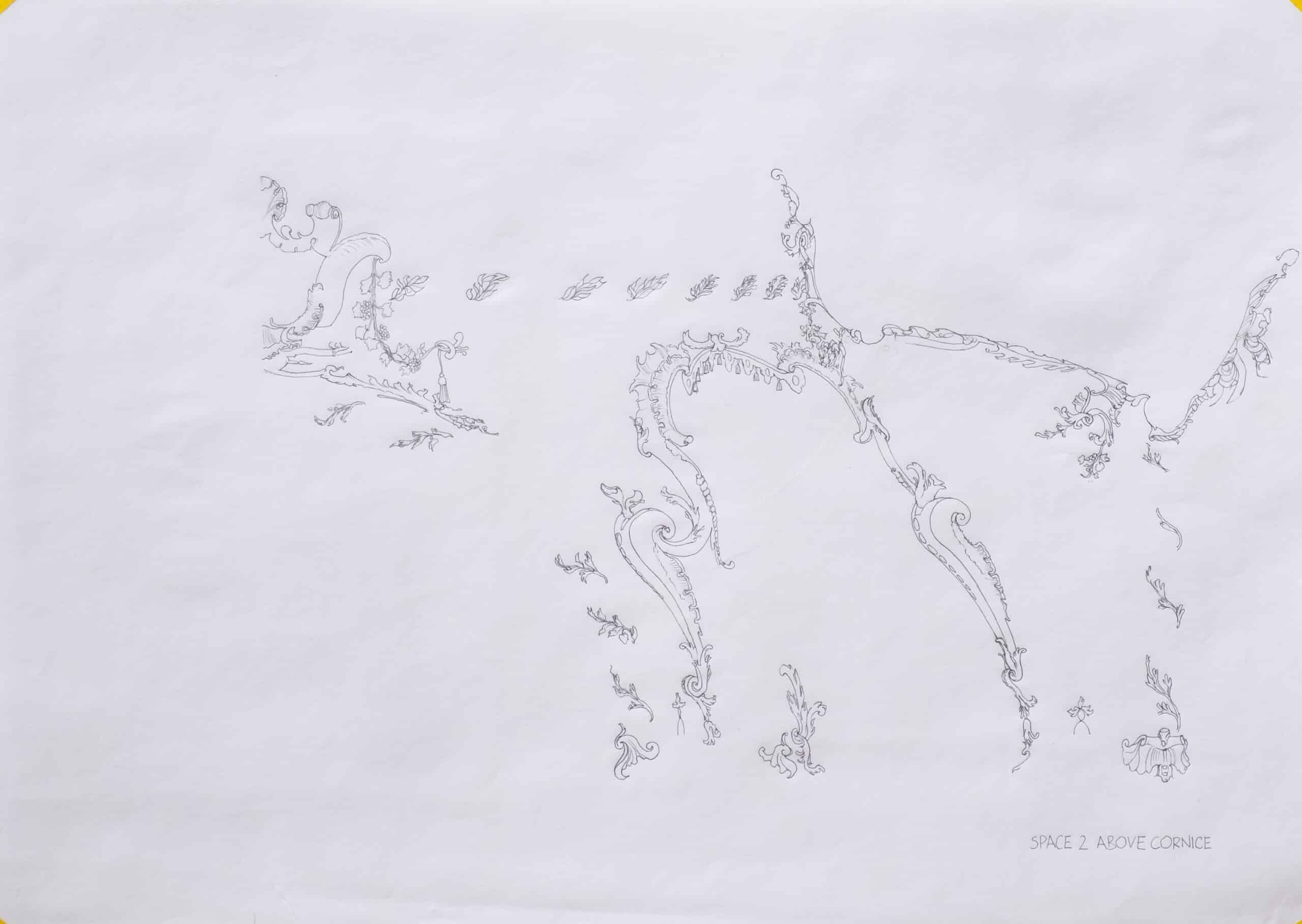
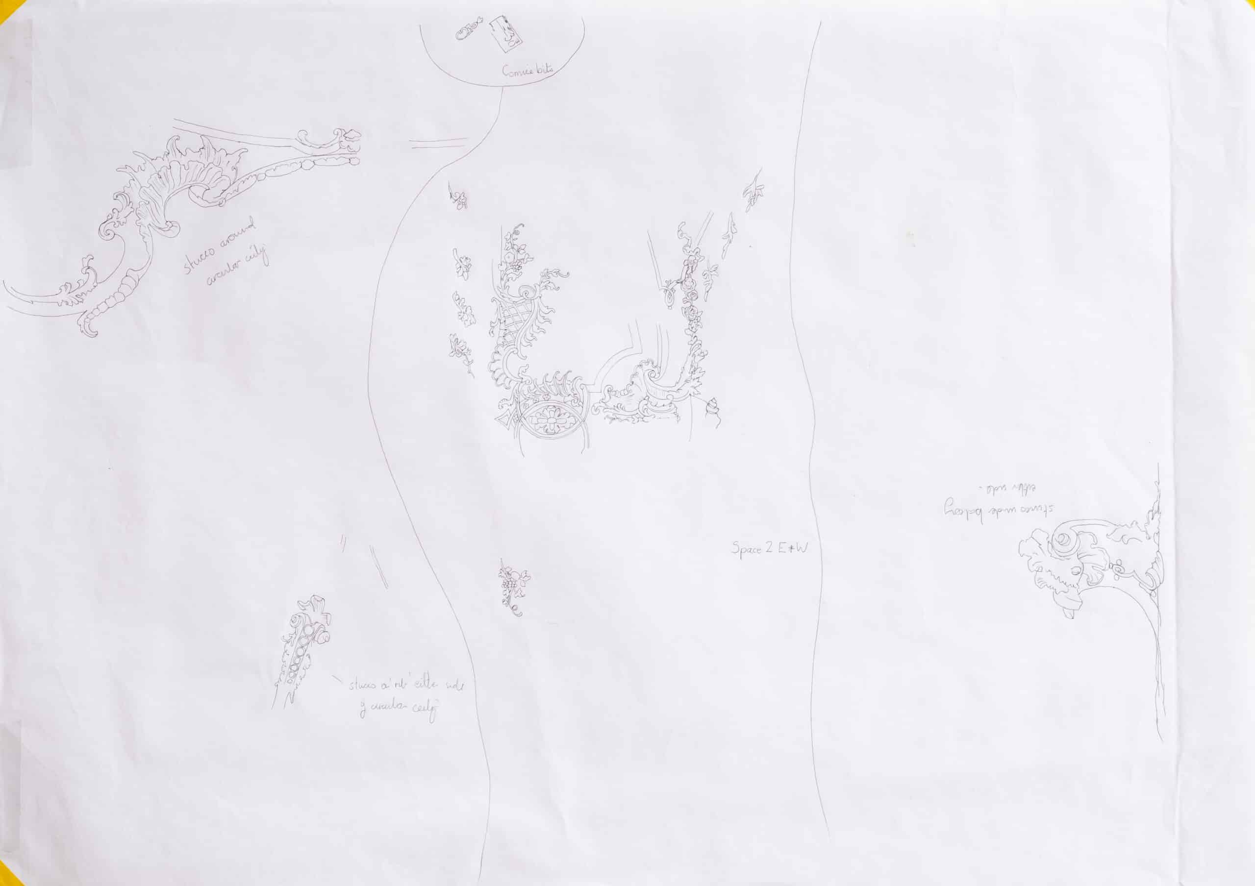
Very little could be taken from scaled photographs in the same manner. Most of the ornament was instead drawn by an iterative process, aided by photographs from many angles using the digitally-drawn framework and sketching as a basis for tracing over. The result is not ‘measured’, but is accurate enough to describe the effect of the interior at the desired scale. That being said, the process would have been more straightforward and the results more accurate if taken from a three-dimensional scanned model of the interior.
After piecing together the four drawings from the digital framework and the hand-drawn elements, each was printed to serve as a base for two overlays – colour and shadow. Both of these were undertaken by hand as tracings over the drawings on separate sheets before being scanned so that they could be added to the collage. The last pieces of the puzzle were the paintings that needed to be incorporated into the section and the vault plan. Photographs taken on site from directly beneath the vaults provided the basis for the frescos. These were applied with some minor corrections to the vault plan, while half of each fresco image was then warped using Adobe Photoshop to fill the section through the corresponding vault.
Assembling the collage
The final process was to combine the digitally-drawn architecture, hand-drawn ornament, shading and colour and the photographed paintings to create a ‘drawing’. Like so many parts of this exercise the process was iterative, working towards an image that would read well, and that would read as an embellished drawing. Again using Adobe Photoshop, the layers of colour and shading were laid over the drawn and photographed layers as transparencies with the white of the paper in both the overlays being used as a means of toning down the photographs and drawings. The contrast, saturation and opacity of the various layers was then manipulated until a satisfactory result was achieved. Lastly, highly translucent black ‘washes’ were added to these two internal views to help grade the depth of the space.
Conclusion
The primary intention in producing these drawings had been to ‘re-present’ the building and the results will be judged on their own merits. However, this study was also an experiment in surveying and drawing methods, in finding the best means to the desired end, in determining what worked and what did not. The collaging process that developed allowed me to use methods of representation most appropriate to the various arts – architecture, sculpture and painting – that are so completely intertwined in this building and its contemporaries. Unexpectedly and unintentionally, the active process of surveying the building, significantly compromised though it was, proved itself to be equally enlightening and worthwhile as a means of discovery, demonstrating the worth of the process of surveying as a research tool and the contribution that it can make to a fuller understanding of a building’s history, as well as its representation.
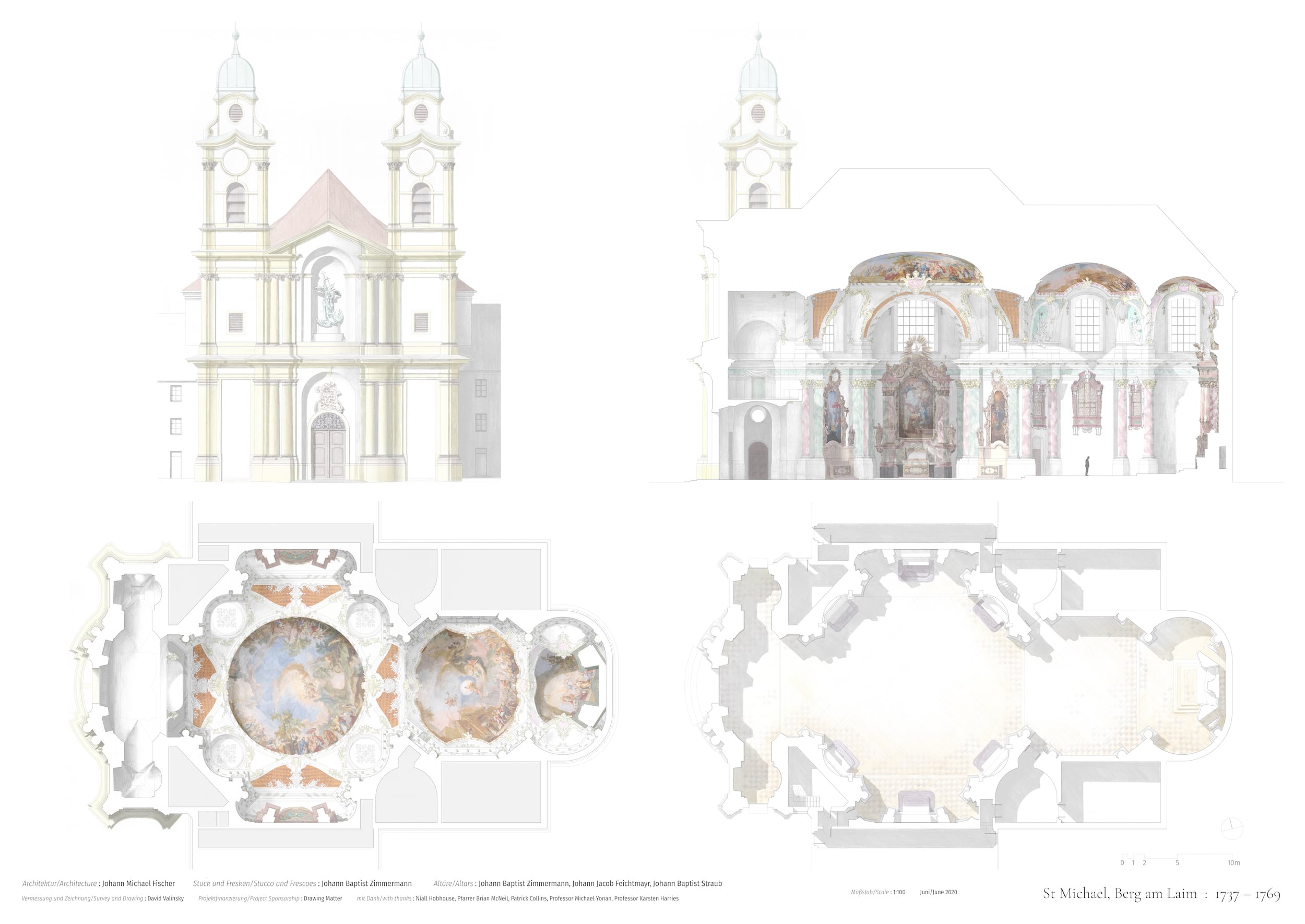
I would like to thank the Drawing Matter Trust and Niall Hobhouse for supporting this project; Pfarrer Brian McNeil for providing such a warm welcome to St Michael; Patrick Collins of Michael Gallie & Partners for the crash-course in surveying; and Professors Michael Yonan and Karsten Harries for their encouragement and support of my rococo survey.
