DMJ – Five Episodes from the History of Drawing Instruments
Instruments of Building in Ancient Rome
Vitruvius, writing in the first century BC, portrays being an architect (architectus) in ancient Rome as a daunting task. The knowledge of the architect, he notes, must encompass the understanding of geometry, engineering, optics, history, philosophy, astronomy, and even music and medicine. At a more practical level, he asks that this super-architect be a ‘skilled draughtsman’ (peritus graphidos) and ‘not unskilled with his drawing instrument’ (graphidos non inperitus).[1] As examples of his own drawing skill, he describes a group of drawings that he had made and presented at the end of his treatise De Architectura which included a detailed diagram and a formula for drawing Ionic volutes with a compass.
Vitruvius’ drawings, now lost, would have been made on papyrus paper. Occasionally, architects used the more expensive parchment for drawing upon, as Aulus Gellius notes in Noctes Atticae (‘Attic Nights’): ‘A number of builders were present, engaged in designing new baths, and showed various kinds of baths depicted on parchment [membranulis].’[2] Although these friable documents have disappeared over time, architectural drawings do survive from Rome and other outposts of the Empire, suggesting that they were widespread if not always commonplace.[3] Known survivals are incised on the stone of building walls or slab fragments, some full-size to the object being created (such as a cornice or pediment), the remainder at reduced scale. The majority were made with crafted tools, with the straight and curved lines showing how well practised the draughtsmen were in the art of using them.
Pompeii, buried in 79CE, has given us proof of such builders’ tools. One of the most important finds is a set of implements, now held in the Naples National Archaeological Museum.[4] Around 1900, the local Chiurazzi Foundry made a reproduction of them, a rather humble item in its extensive catalogue of bronze casts of ancient objects.[5]
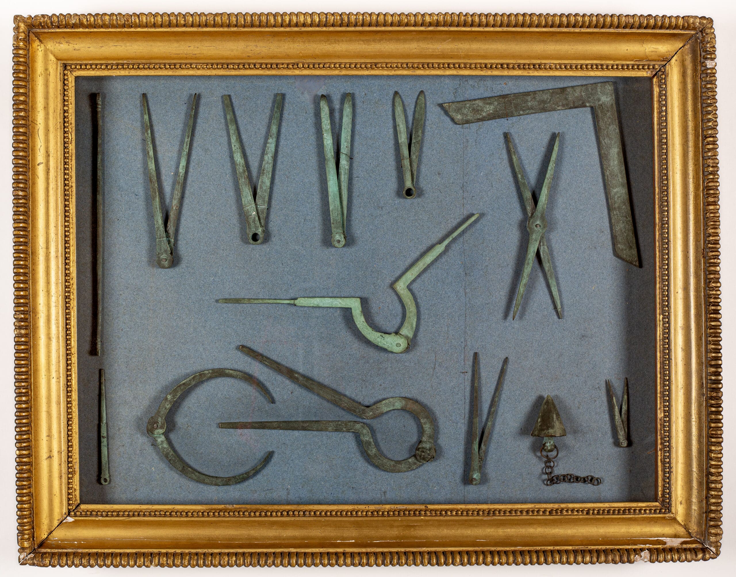
The assortment is very much an on-site kit. The bronze Chiurazzi set—patinated green with oxidisation and now in the Drawing Matter Collection—principally consists of measuring instruments: a compass, a series of callipers with their bowed arms to measure outside forms like masonry, and a pair of foot rules with articulated arms and a locking device, each half of the standard Roman foot but opening out to a full foot (29.57cm). There is also a set-square, for ensuring the accuracy of right angles. For verticals, there is a plumb bob replete with part of its chain. The most interesting tool, in terms of drawing, is a pair of styli with sharp-pointed iron rods for making lines in a wax tablet—a common writing surface of the ancient world—suggesting that the owner of the set could write, or at least draw.
This set belonged to a builder of more refined standing than that of the stonemason Diogenes, a neighbour who affixed a limestone relief sign to a wall depicting his tools of the trade: a wedge, a hammer, a chisel and a levelling square, showing his involvement with heavy work, all, typically for Roman culture, accompanied by a fascinus—a phallus to ward off the evil eye.

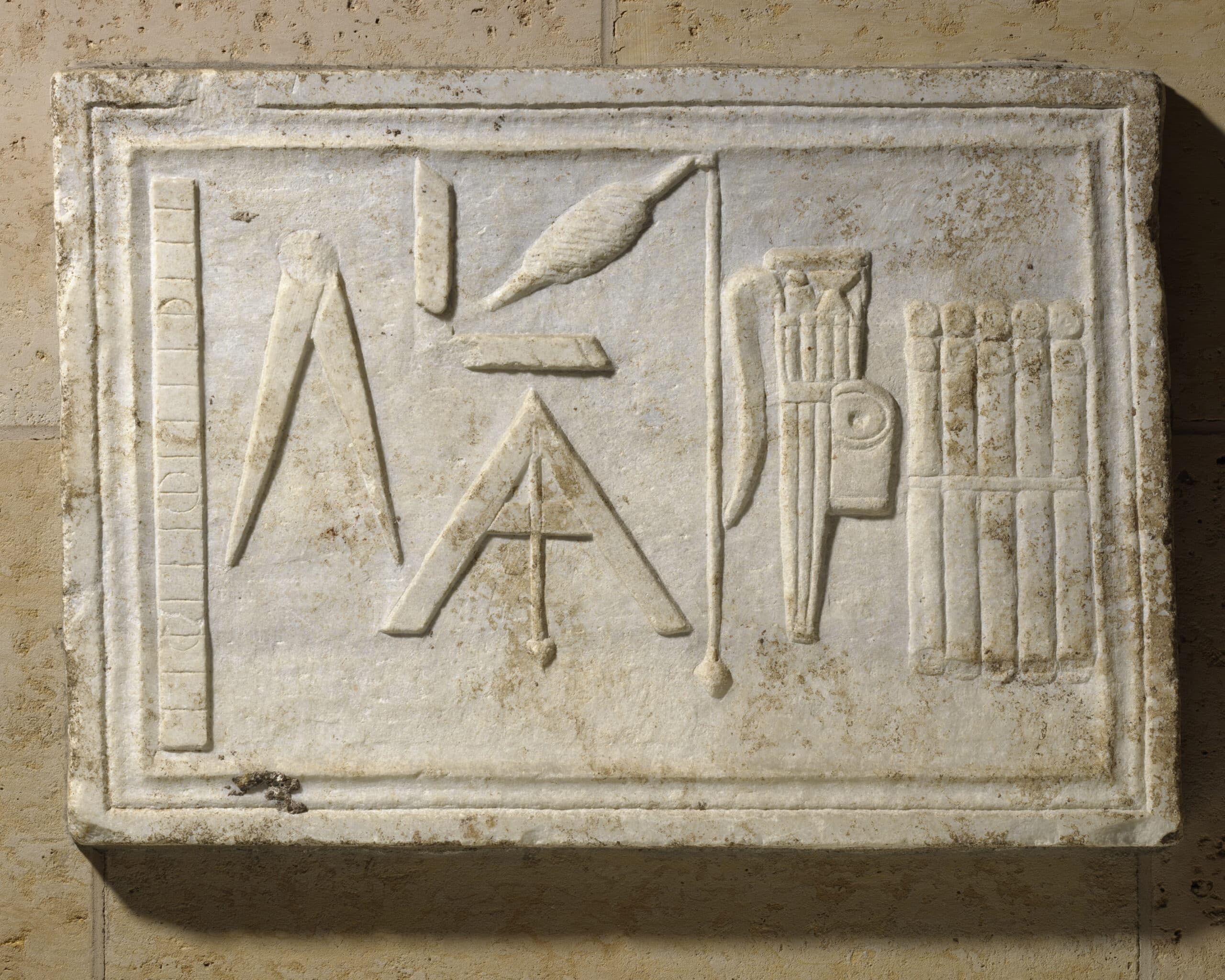
Roman builders sometimes had their funerary stones embellished with instruments like Diogenes’. A similar example to the Pompeii tool set, currently in the Nelson-Atkins Museum of Art in Kansas City, Missouri, is a carved Roman marble relief with writing/drawing instruments, demonstrating a more educated approach to building design.[6] Alongside precision implements like a graduated rule, a compass and a (damaged) square, nearly half of the plaque is taken up with writing materials: a portable writing case attached to a belt clip containing an iron stylus and a reed pen for dipping into the ink well that is fastened to the case. A bundle of scrolls—long sheets made of papyrus—is part of the set. These could have been used for contracts, financial accounts or architectural drawings. If the owner was not quite the exemplary architect portrayed by Vitruvius, they were at least a builder (structor) with the skills of a master.
Notes
- Vitruvius, On Architecture (Cambridge, MA: Harvard University Press, 1995 [1st edn 1931]), 8–9. Trans. Frank Granger, with amendments by the author. Granger uses the common translation of graphidos as ‘pencil’, although there were no pencils in the ancient period as we know them today.
- Aulus Gellius, The Attic Nights of Aulus Gellius, vol.3 (Cambridge, MA: Harvard University Press, 1970), 387. Trans. John Carew Rolfe, with amendments by the author.
- For an inventory of all known surviving Greek and Roman architectural drawings, and references in ancient literature, see Antonio Corso, Drawings in Greek and Roman Architecture (Oxford: Archaeopress, 2016).
- Photo illustrated in Jean-Pierre Adam, Roman Building: Materials and Techniques, trans. Anthony Mathews (London and New York: Routledge, 1994), 68.
- Fonderie artistiche riunite J. Chiurazzi & Fils, S. De Angelis & Fils: società anonima. Bronzes, Marbres, Argenterie, catalogo di vendita (Naples: Officina tipografica Ferrucio Lazzari, 1911), 42.
- Robert Cohon, ‘Tools of the Trade: A Rare, Ancient Roman Builder’s Funerary Plaque’, Antike Kunst, vol.53 (2010), 94–100.
The Medieval Master Mason’s Giant Compass
The giant drawing compass seems more like a mythical tool than a historical one. In those rare instances in which medieval master masons appear in illustrated manuscripts, they are shown wielding an outsized pair of iron compasses. How many of them actually acquired such giant compasses is uncertain—no examples are known to survive.[1]
The outsized compasses served as a symbol of the master mason’s high office, depicted in manuscripts larger than the sceptre of the kings whom the master is often seen to be attending. In medieval iconography, only God might be seen to wield a bigger pair of compasses—but then he did have the greater job of creating the heavens and the earth.


Giant compasses, like the smaller and common compass-divider, were used by stone masons to delineate arcs and circles. Employing such a large tool for making full-scale measurements and drawings was an advancement on the ancient practice of using a peg, a rope and a drawing point. When using the hand-size compasses, with paper not yet readily available and parchment expensive, drawing surfaces were by nature ephemeral. Most drawing surfaces were manageably small—a smoothed patch of dirt or a stone slab. In more sophisticated settings, trestle tables coated with soot or skimmed with a thin plaster surface were used. These were often found in temporary drawing-office rooms, erected during construction and either dismantled after use or put to work for other purposes.[2]
If exact measurements for full-size details were required, such as that of a large window, then the drawn image had to remain present for the duration of the works to allow the masons to deduce measurements from it. This is where the giant compasses came into play. In Europe, two of the best surviving examples of their use can be seen in England: one is located in Wells Cathedral, and the other, and finer, is in York Minster.[3] Up a narrow twisting staircase and through a small wooden door high above the Chapter House vestibule is the remarkable drawing office, dated between 1350 and 1500, with its tracing floor filled with etched patterns. This has been preserved in good condition, only because the room was largely abandoned and used for storage.[4]
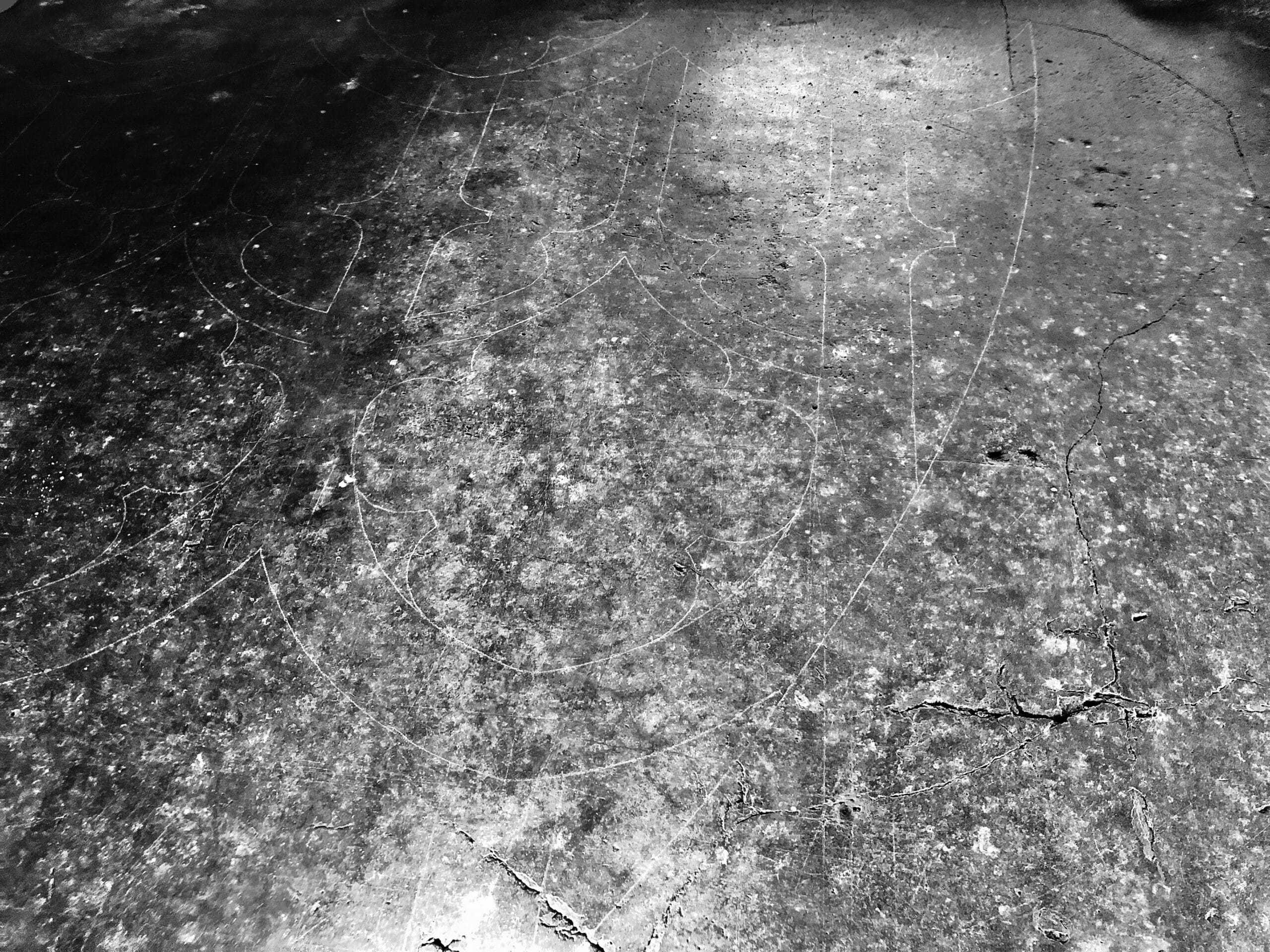
Hundreds of fading white lines cover the plaster floor of York Minster. The largest design is for a three-metre pointed arch, made with a giant compass by a master mason skilfully sweeping and grinding its spiky tips into the floor surface, its pattern echoing the tracery of an aisle window in the Minster. The dark plaster surface would have been constantly renewed, skimmed over with a new thin layer of gypsum, or the cuts simply rubbed down, enabling the giant compasses to make their multiple marks on the floor.
Notes
- The following reference the use of the giant drawing compasses: Jan Svanberg, Medieval Masons (Uppsala: Carmina, 1983), 121; Anthony Gerbino and Stephen Johnston, Compass and Rule: Architecture as Mathematical Practice in England, 1500–1750 (London and New York: Yale University Press, 2009), 21; Louis Francis Salzman, Building in England down to 1540 (Oxford: Clarendon Press, 1952), 16.
- L.R. Shelby, ‘Medieval masons’ tools. II. Compass and square’, Technology and Culture, vol.6, no.2 (Spring 1965), 243–44.
- My thanks to John David, Master Mason of York Minster, for showing me the tracing floor of the drawing office in York Minster and for sharing his skilled expertise.
- John H. Harvey, ‘The tracing floor of York Minster’, in The Engineering of Medieval Cathedrals. Studies in the History of Engineering, vol.1, ed. Lynn T. Courtney (Aldershot: Ashgate, 1997), 81–86. (Reprinted from Friends of York Minster, 40th annual report [York: 1968], 1–8). John H. Harvey, ‘Architectural history from 1291 to 1558’, in A History of York Minster, eds G.E. Aylmer and Reginald Cant (Oxford: Clarendon Press, 1977), 149–92.
An Architectonic Sector Fit for a King
In the late 18th century, at the height of the classical revival, attention to the complex act of delineating measured architectural orders reached a zenith. Weighty illustrated treatises were published showing methods for drawing the proportions of antique elements, from columns to entablatures, mouldings to balustrades. A Treatise on the Decorative Parts of Architecture (1759) by William Chambers was to become one of the most famous of these works.
But would it not have been easier if an architect possessed a drawing instrument that could provide measurements of the dimensions of the orders? A few skilled specialists set about designing such instruments, with the ‘architectonic sector’ created by Joshua Kirby about 1761 being both the most remarkable and the most complex.[1]

Joshua Kirby and William Chambers were associates, both tutors to George, Prince of Wales, who in 1760 became King George III. Chambers was his architectural mentor, and Kirby a drawing master. George was keen on the discipline of architecture with his wide interest in the arts and sciences. A collection of fine architectural drawings of classical temples and residences produced by him, made with the guidance of his coaches, is held in the Royal Collection.[2] Kirby, primarily a painter, had been bolstered in his profession through his friendship with Thomas Gainsborough, who painted a full-length portrait of him and his wife, now in the National Portrait Gallery, London. Kirby was to turn his attention to perspective, publishing on a new system that he believed steered away from pure mathematical formulation to how things ‘appear to the eye’.[3] He shared his observations on the visual power of perspective with his friend William Hogarth, who was at the time writing his Analysis of Beauty (1753), an aesthetic treatise advocating for the role of natural forms in artistic compositions while critiquing the recognised academic positions of the art establishment.
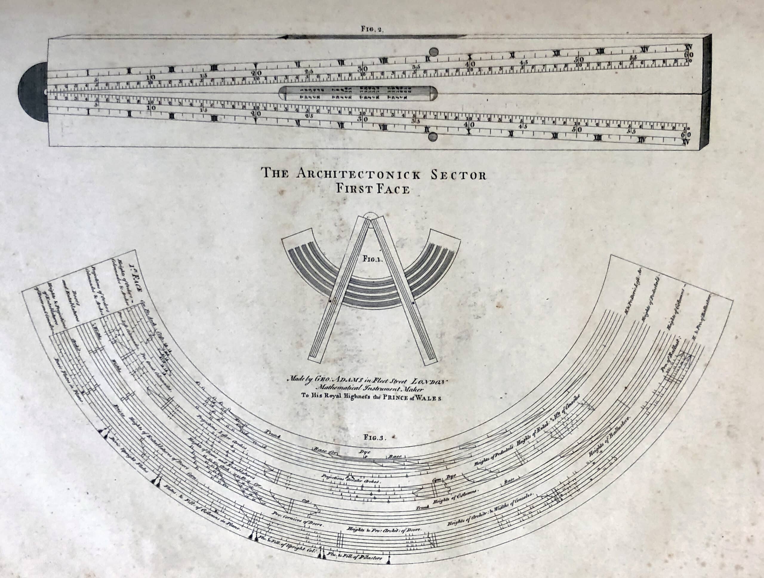
Contrary to Hogarth’s interests and ideas, Kirby’s architectonic sector is an instrument of control, immersed in regulated methods of applying architectural proportions. The hinged 12-inch-long instrument is marked by numbered divisions and made to slide over a broad crescent, the ‘limb’, which details parts of a classical building. Following Chambers’s treatise, Kirby’s architectonic sector concentrates on the five orders of architecture—Tuscan, Doric, Ionic, Corinthian and Composite—and arranges these in staves akin to the five lines of musical notation.
Kirby’s device was accompanied by a handbook on how to use it, with a frontispiece designed by Hogarth, and dedicated to King George—another weighty tome in the genre of mathematical instruments.[4] In fact, the King took such a close interest in the use of the instrument that he transcribed a draft of Kirby’s manual before publication, 32 pages long, making edits to the text as he went along, all of which were accepted for printing.[5] However, the sector proved so intricate to use that few were made. Also, it would have been expensive to produce, another reason for the small number known to exist, all made by the famous instrument-maker of the day, George Adams senior. The most beautiful two are a full silver version in the RIBA and a silver and ivory example in the Science Museum (reproduced on the cover of this issue), both exquisitely engraved, one of which probably belonged to the King.[6]
Notes
- Kirby’s architectonic sector is discussed in Maya Hambly, Drawing Instruments 1580–1980 (London: Sotheby’s, 1988), 137–42, and Anthony Gerbino and Stephen Johnston, Compass and Rule: Architecture as Mathematical Practice in England 1500–1750 (New Haven and London: Yale University Press, 2009), 131–42.
- David Watkin, The Architect King: George III and the Culture of the Enlightenment (London: Royal Collection, 2004); Felicity Owen, ‘Joshua Kirby’, The Oxford Dictionary of National Biography, 3 January 2008 (Oxford University Press): https://www.oxforddnb.com/display/10.1093/ref:odnb/9780198614128.001.0001/odnb-9780198614128-e-15646 [accessed 5 January 2024].
- Preface to Joshua J. Kirby, Dr Brook Taylor’s Method of Perspective Made Easy, Both in Theory and Practice (London: Printed by the Author, 1754). Also, see Eileen Harris and Nicholas Savage, British Architectural Books and Writers 1556–1785 (Cambridge: Cambridge University Press, 1990), 254–58.
- Joshua J. Kirby, The Description and Use of a New Instrument Called, an Architectonic Sector. By Which Any Part of Architecture May be Drawn with Facility and Exactness (London: R. Franklin, 1761).
- Royal Collection Trust, George III Essays: Geo/Add 32/1742–1760. My thanks to Julie Crocker, Senior Archivist, Royal Archives, for her observations on the manuscripts.
- John R. Milburn, ‘Adams family (per. 1734–1817), The Oxford Dictionary of National Biography, 3 January 2008 (Oxford University Press): https://www.oxforddnb.com/display/10.1093/ref:odnb/9780198614128.001.0001/odnb-9780198614128-e-49854 [accessed 5 January 2024].
Stanley’s Treatise on Drawing Instruments
In 1866, following in the long tradition of scholarly treatises that includes Vitruvius, William Stanley (1829–1909) self-published his accurately titled A Descriptive Treatise on Mathematical Drawing Instruments, Their Construction, Uses, Qualities, Selection, Preservation, and Suggestions for Improvements; With Hints upon Drawing and Colouring. By its seventh edition, in 1900, Stanley had added 120 pages, including new illustrations of drawing and engineering instruments. The treatise became a well-known textbook and catalogue worldwide—scientifically instructive and well-illustrated, it was consulted by architects, engineers, surveyors, technicians, students and many more gaining experience in making technical drawings. Stanley hoped it would be understood by workmen, traders and professionals.


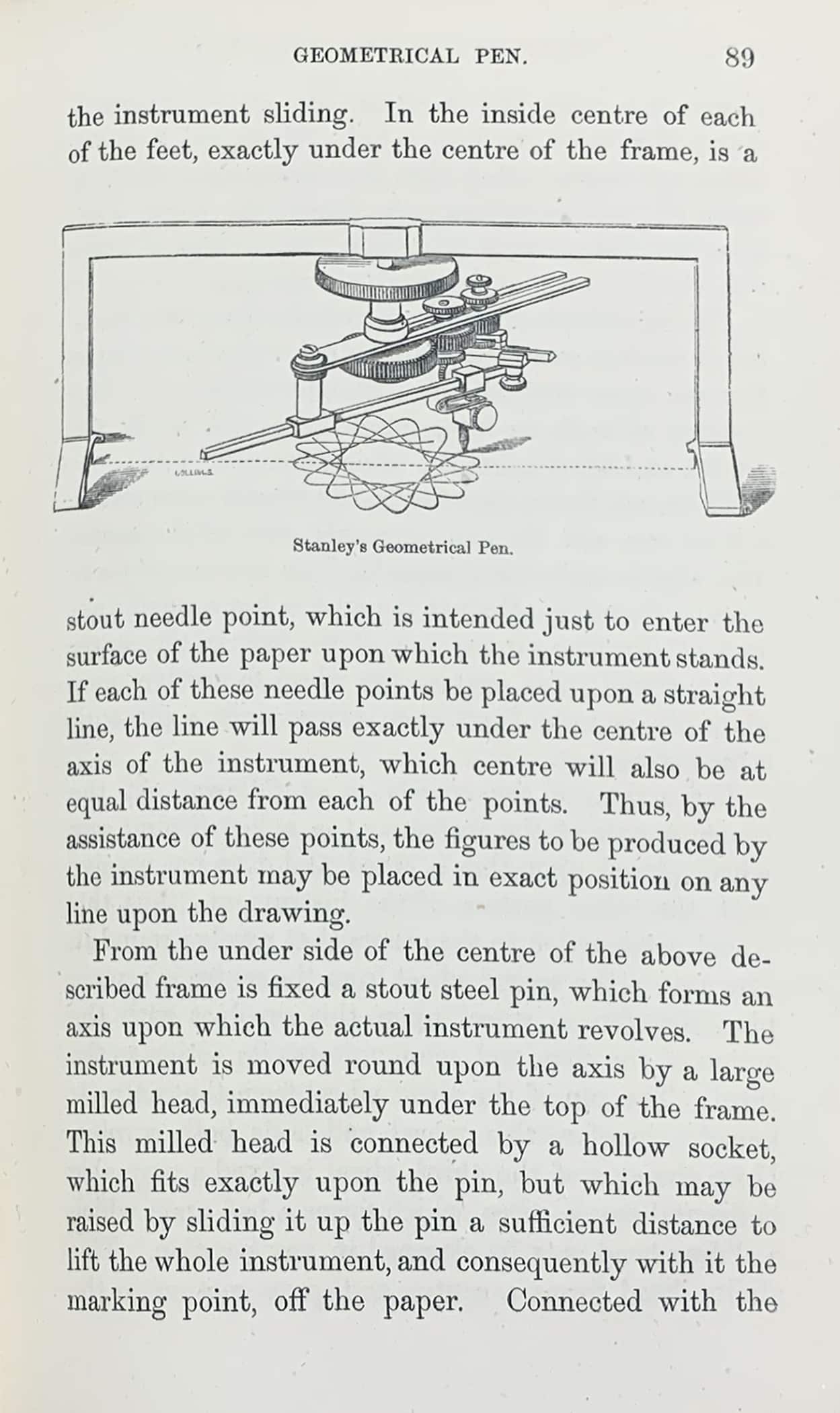

The book reflected its author’s great scientific knowledge and ability in the design of instruments, as well as an astute business acumen. The year before the first publication of the treatise, Stanley had set up a thriving factory manufacturing metal instruments. A decade before, he had started making wooden implements, including a T-square (then spelled ‘tee-square’) that—with its tapered blade, which was light and easy to manipulate—became one of the most used drawing tools (and continues to be so, for those who use them today).[1] From the very first edition, Stanley listed the sales price of each of the instruments at the back of the volume. By 1900, although there were over 225 of these pieces itemised, this was but a small percentage of the 3,000 instruments that he was manufacturing in South Norwood, London.[2] The commercial success of his enterprise led Stanley to list the company on the Stock Exchange that year.
Stanley wrote with humility, respectful of both past and contemporary instrument-makers, often referencing the influential instruments produced by George Adams Senior and the book Geometrical and Graphical Essays (1791) by his son George Adams Junior. There were a few instruments to which Stanley did not make modifications, and newly patented tools were often compared to their previous versions. He also admitted the failures in some of his experiments, such as his attempt to improve the design of a double-jointed bow compass.
Today, many of Stanley’s drawing instruments may be perceived as bizarrely anachronistic—like surreal mechanical creatures taken from the science-fiction pages of steampunk novels. Perhaps Stanley’s ‘oograph’, an idiosyncratic instrument for drawing the eggs of birds that he created for an oologist friend, might still find use today by researchers searching for the perfectly shaped, genetically modified egg.
Notes
- Anita McConnell, ‘William Ford Robinson Stanley’, The Oxford Dictionary of National Biography, 23 September 2004 (Oxford University Press): https://www.oxforddnb.com/display/10.1093/ref:odnb/9780198614128.001.0001/odnb-9780198614128-e-36250?rskey=gWI1BP&result=5 [accessed 5 January 2024].
- Jane Bruccoleri, ‘Longlasting Legacy’, Croydon Guardian (12 July 2006): https://www.yourlocalguardian.co.uk/news/features/830846.Longlasting_legacy [accessed 30 November 2023].
Zaha Hadid and the Ship Curve
Can a drawing tool generate an architectural movement? In the last two decades of the twentieth century, when handheld instruments still reigned supreme and computer-aided drawing programmes were in their infancy, Zaha Hadid employed the arced edge of a ship curve to inscribe flowing bowed lines in her drawings—lines that were further translated in her paintings and designs of buildings to produce a style later recognised to be uniquely hers.
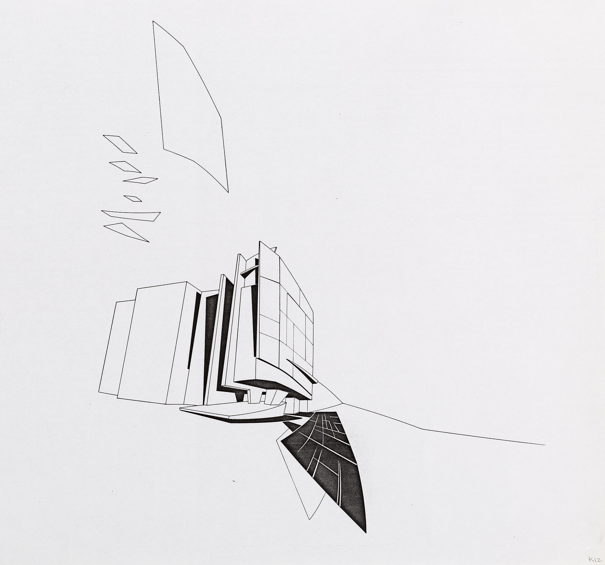
In 1982, Hadid was working with assistant Michael Wolfson, whom she had tutored at the Architectural Association in London. The pair travelled to Paris where they purchased an acrylic ship curve. This was a tool whose two sides were curved slightly differently. One end of the instrument resembled a beaked bird’s head with an ‘eye’, a hole for pinning the drawing tool to the drawing board. These pattern-making templates had been manufactured since 1800, and historically were principally used for shipbuilding. When smaller versions with tighter curves made an appearance they became suitable for broader use, from dressmaking to engineering and architectural drawing. These are now known as French curves.
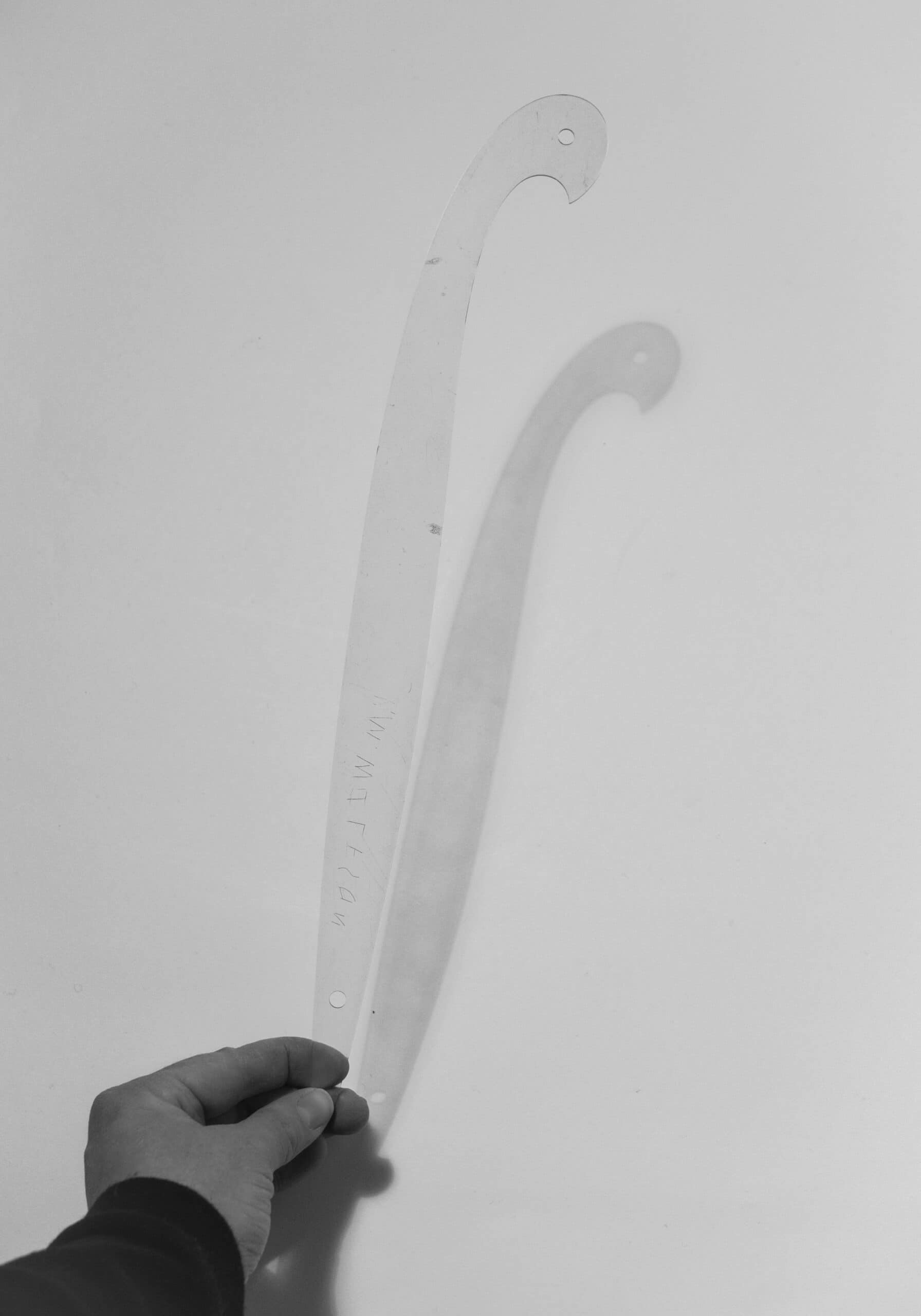
The ship curve quickly became a common drawing tool in Hadid’s office, fostering her experiments in the making of ‘the continuous line’.[1] For the early project of the Peak Leisure Club in Hong Kong, a competition entry that dates from 1982, Hadid and her collaborators used the ship curve to create a set of perplexing yet beautiful drawings and designs, strange and suggestive of early-20th-century Suprematism (the work of Malevich had a decisive influence on her). The ship curve made the warping of the imagined skyline of Hong Kong possible, as well as the swooping lines of the club building perching on the mountainside.
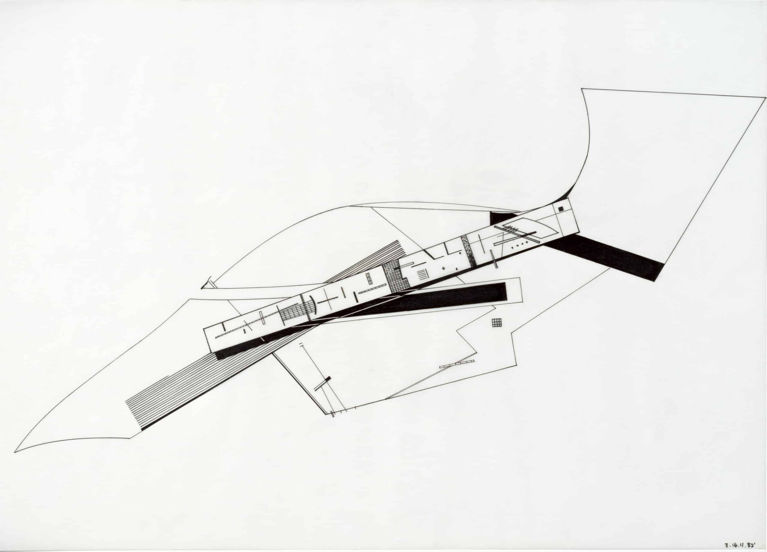
As computer-aided drawing software entered Zaha Hadid’s office, Hadid was able to manipulate her continuous line in unexpected ways, while still producing hand-drawings. From 2003 until her death in 2016, Hadid was assisted by the architect Antonio de Campos, who had worked briefly for her in the early 1990s, but now rejoined as her principal perspectivist. Working between digital and analogue drawings, de Campos reinforced Hadid’s reign as ‘Queen of the Curve’.[2] Together they explored even further the various forms of the curve, as de Campos experimented with preparatory drawings and models as well as larger acrylic paintings during the final stages of a proposal. In the translation from the digitally created lines of these drawings to the analogue ones, de Campos returned to the humble ship curve to reconstruct and represent the fluidity of Hadid’s architectural style.[3]

Notes
- ‘Plane Sailing: Zaha Hadid RA on the influence of Malevich in her work’, RA Magazine (Summer 2014), https://www.royalacademy.org.uk/article/zaha-hadid-ra-on-the-influence-of [accessed 30 November 2023].
- Caroline Davies, Robert Booth and Mark Brown, ‘“Queen of the Curve” Zaha Hadid dies age 65 from heart attack’, The Guardian (31 March 2016), https://www.theguardian.com/artanddesign/2016/mar/31/star-architect-zaha-hadid-dies-aged-65[accessed 30 November 2023].
- The author would like to thank Michael Wolfson and Antonio de Campos for their generous information.
Neil Bingham is an architectural historian and curator specialising in the history of architectural representation and modern design. He is a former curator of architectural collections at the Victoria & Albert Museum, the Royal Academy of Arts and the Royal Institute of British Architects. His books include Patrick Gwynne (2023); Mark Fisher: Drawing Entertainment (2021); 100 Years of Architectural Drawing: 1900–2000 (2013); Masterworks: Architecture at the Royal Academy of Arts (2011); Wright to Gehry: Drawings from the Collection of Barbara Pine (2005); The New Boutique: Fashion and Design (2005); Modern Retro: Living with Mid-Century Modern Style (2000); Christopher Nicholson (1996) and C.A. Busby: Architect of Regency Brighton and Hove (1991).
The article is included in the second issue of DMJournal, Drawing Instruments: Instrumental Drawings.
